Member
Joined 2009
Paid Member
If I decide to use the protection circuit I may be able to add delayed start. In simulations without the protection there is almost no start-up thump, in reality it will not likely need any kind of delay, as Nico has reported. I'm thinking about whether I can incorporate the solid state relay onto the pcb, probably on the underside as an option. I need more time to consider this, it would be very convenient.
May-i suggest you bring as much protection circuit as possible away from the amps itself ? Like that, if any annoyance, delay needed, instant cut of the Speakers at cutoff, desire to change the solid state relay for a mechanic one etc... you can modify your protection board without modifying your precious amp ?
Just a little flat wire connector to bring the differential signal to this separate protection board, via some thin flat cable ?
What is the serial resistance of your Solid state relay ? As i said i'm not partial of it for basses loudspeaker where Damping factor is an issue, but i think it would be the best option for medium and tweeters ? Faster and safer for most fragile units, where damping is not an issue.
That's just gave-me an idea. Using parallel solid state and mechanical relays for basses. Well... mechanical relay will take a little time to open (some mS). And we want the mechanical relay just reduce the serial resistance of the SS one and solid state takes the sparkles for itself So it is just a matter to detect if any differences on the two sides of the mechanical relay to be sure it has opened before opening the SS one without adding any supplementary delay. Best of the two worlds.
Last edited:
Member
Joined 2009
Paid Member
If it's something simple enough that can fit on the board, then it's an option, doesn't mean I have to fit those parts. The benefit is simplicity, one pcb, no messing around. If I decide to go with separate pcb I will likely make a more universal design that isn't tailored to this amplifier.
I believe the on-resistance of modern MOSFETs can be very low, insignificant for damping factor considerations.
I believe the on-resistance of modern MOSFETs can be very low, insignificant for damping factor considerations.
Hum, a 500 damping factor on a 8ohm speaker means 16 mOhms. If you don't want to destroy-it more than, says, 10% :1,6 mOhms. Possible ?I believe the on-resistance of modern MOSFETs can be very low, insignificant for damping factor considerations.
The best i know are, for 60V: 1.7 mOhm each, and for 75V: 2.3mOhms each. Means double. Paralleled can be an, expensive, alternative.
I love the idea to can reuse parts when i change something in my system ;-)IIf I decide to go with separate pcb I will likely make a more universal design that isn't tailored to this amplifier.
Please can you indicate the exact connection of your protection circuit on the amp side ? Did-you simulate all the possible failure cases of the amps components and power rails ?
Last edited:
To achieve a damping factor of 500 for an 8ohm speaker the total resistance plus output impedance of both the Flow and Return halves of the circuit must add up to 16milli-ohms.
Have you measured the resistance of the PCB traces? or the lead out wires, or the terminal connections, or the speaker cables, or the speaker connections or the speaker internal wiring to the crossover or the crossover resistance, or the wiring from crossover to driver, or the driver terminals?
You are asking virtually the impossible to maintain a DF of 500.
Using sensible resistance values for the complete speaker circuit you may find that the total resistance is well over 100milli-ohms and sometimes approaching 0r5.
10milliohms of extra resistance from either or both a SS relay or a mechanical relay will have virtually no effect on the low frequency response of virtually all normal or active speaker drivers. The effective DF could be 80 for 0r1 of circuit resistance and this would degrade to an effective DF of 72.7 for that extra 0r01 of relay resistance.
Member
Joined 2009
Paid Member
I'm not sure how much damping factor is needed ? my tube amp sounds very nice to my ears, it has no nfb, the damping factor isn't very high. If extreme DF is needed, the protection relay can be included inside the nfb loop.
No way, you will loose delay speaker-on, and need a total restart of your system if the protection fire: You will be in open loop if the relay open.If extreme DF is needed, the protection relay can be included inside the nfb loop.
@AndrewT
About PCB traces, it is a matter of good design: You have to take the Cr line right on the Loudspeaker soldering holes. And have the traces from the sources/emitters to this point perfectly equal in lengh and size and symmetrical on all the power mosfets/transistors, as well as the lines from power rails to emitter/drains. It can act on the distortion on a factor of 10.
I remember a technical journalist asking us in the same sentence, 40years ago, how did we succeed a 0.05% distortion factor (rare at this time) on a cheap 2X50w commercial amp, and why this little PCB trace running parallel to the loudspeaker out's one on few centimeters, coming from the same point ;-)
Member
Joined 2009
Paid Member
For a generic protection circuit there are lots of considerations. For TGM5 I should try and stick with the simplest way to get the level of protection I want and not try to do too much first off.
To be honest, I am not worried about DF. I'm not convinced that a high DF is even desirable. It's not a consideration for me.
My main issue is speaker protection - perhaps simple dc protection is the best option, these kinds of circuits are more mature and more likely to serve my needs without needing to do prototyping. I'll take a look a this.
Member
Joined 2009
Paid Member
I have decided not to implement a protection circuit based on comparing input to output. I really like this idea, but I don't think it's ready and needs more prototyping.
A simple dc-protection circuit (from Rod Elliot) is lower risk, it is a proven approach. And an over-current protection circuit based on monitoring the voltage drop across the output emitter resistors is another proven approach. Both carry consequences on sound quality during transients if not set up properly, but the functionality is well understood.
Latching the solid state relay function when a fault condition is detected is another low risk circuit element.
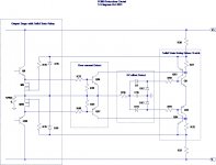
I've attached my latest thinking. It has one controversial feature. I have placed the FETs that form the solid state relay inside the global nfb loop so that any impact on sound quality can be reduced. I don't think this is necessary, but it costs nothing to do so. The issue is that I've used the on-resistance of the FETs to substitute for emitter resistors.
A simple dc-protection circuit (from Rod Elliot) is lower risk, it is a proven approach. And an over-current protection circuit based on monitoring the voltage drop across the output emitter resistors is another proven approach. Both carry consequences on sound quality during transients if not set up properly, but the functionality is well understood.
Latching the solid state relay function when a fault condition is detected is another low risk circuit element.
I've attached my latest thinking. It has one controversial feature. I have placed the FETs that form the solid state relay inside the global nfb loop so that any impact on sound quality can be reduced. I don't think this is necessary, but it costs nothing to do so. The issue is that I've used the on-resistance of the FETs to substitute for emitter resistors.
Attachments
Hi Gareth
I also like more this approach because it detects anomaly at output pin if it is higher than certain level, so less parameters to consider the more secure the protection result. I have only one thought about mosfet solid state relay or any kind of relay at output, I never use them, I always rapidly shut-down the output transistors to high Z, so among analog linear behavour they also act as an on/off switch for the speaker. 🙂
I also like more this approach because it detects anomaly at output pin if it is higher than certain level, so less parameters to consider the more secure the protection result. I have only one thought about mosfet solid state relay or any kind of relay at output, I never use them, I always rapidly shut-down the output transistors to high Z, so among analog linear behavour they also act as an on/off switch for the speaker. 🙂
Member
Joined 2009
Paid Member
You're right, simple over-current protection of the output devices can be implemented within the output stage instead - I guess this is the traditional approach and has been proven out over the years. However, it doesn't help with dc damage to the speakers though, since that's likely to have been a result of an output device failure - perhaps a simple crowbar is all that is needed. I'll give that some thought.
Look my last versionYou're right, simple over-current protection of the output devices can be implemented within the output stage instead - I guess this is the traditional approach and has been proven out over the years. However, it doesn't help with dc damage to the speakers though, since that's likely to have been a result of an output device failure - perhaps a simple crowbar is all that is needed. I'll give that some thought.
http://www.diyaudio.com/forums/digi...sures-class-d-system-project.html#post2737393
Notice: it has proven any short circuit on a dangerous level for the output devices is detected. The idea to be added, in case of short circuit, is to simply short circuit the input signal: the speakers are yet well protected by the short circuit itself, and the power devices protection need only to deliver less current to be safe: this is achieved if no input signal, means no output current. Right ? So no need to any device in the amp itself with their negative impact on sonic quality. And, if you use a mechanical relay, and shot circuit the input signal with some Mosfet, the signal will have disappeared before the relay began to move ans sparkle.
I will go for SS relay paralleled with Mechanical ones.
About sonic impact of the relay itself, in my amp, i'm unable to listen any difference (don't know with Static relay). So ?
Last edited:
I do not think so, Andrew. As long as your Op amp is fast enough and impedances low enough for the parsitic caps of the input fets. And i don't think there will be a difference between any kind of solution running on this idea.I think the phase difference between input and output is a problem with Esperado version. That's possibly why he has to turn down the sensitivity to prevent false triggering.
30 years ago, when i made the first realization of this, i tuned my protection on a resistive load. And it fired under 100mv of DC in the output. and not under musical program. Once connected on loudspeaker, it fired at very low level of music. Then i took a look to the error signal, and i was astonished ! Owfull !!!
Of course, i've looked to the CR to see what's happened in the amp itself: Same shame. On complex charges with selfs and caps and with motional reactions, an amplifier, as good as it is is painfull with transients. And carry a lot of error signals in the CR. Just take a look at your amp on the two side of the C.R. resistance coming from output with no sound, and just move the loudspeaker's cone, you'll see.
Well, in the same time, who care about 100mV of DC ? I believe my actual tuning will fire around less than 2V of DC, and very near after the beginning of clipping. And in mili Sec, the most fragile tweeter will never, never turn even hot for something else than Led Zep !
It is sensible enough to have suffered hundred of short circuit for demonstration purposes without failure. (The sharp on the screw driver can be affraying !)
Remember too that, if your amp is dancing with DC offset, this error will be added, so you'l need to take extra margin for this too, not an issue.
I believe that no other protections, integrating signals to detect DC, for example, will give 10 time less sensibility, and 100 time more delays ! Many of them do not react fast enough, if out is on the bad DC rail, your loudspeaker moving coil can hit the plate at the bottom of the magnet, and CrZZZ crZZ. Here, you will hardly hear a little "clok" before silence.
[edit]
Ooops, am-i crazy, or your message had disappeared ?
Last edited:
Crowbars have sure proven cost-effective protection for pro. speakers in PA applications. In one-off small amps with standard wire fuses, it will likely mean a whole output stage replacement every time it fires. At the least, this will be expensive to prove, before considering any real benefit once adjusted to trigger correctly. 🙁Y - perhaps a simple crowbar is all that is needed. I'll give that some thought.
'Sure you you want do this?
Last edited:
Member
Joined 2009
Paid Member
No I'm not sure. I'm having fun learning and exploring about amp protection. It's slowing down the project but I was hoping there was a simple solution that I could fit on the same pcb as the amp and have an all-in-one solution.
If I implemented a crow-bar I'd also put current limiting on the output power devices. Not SOA protection, but a high current limit that really only came into action with a shorted output so that there would be no impact on the sound quality during transients. If the crow-bar was false triggered the current limiter would save the output from destruction and likely also it would save the crow-bar; this would also allow me to 'test' the protection safely. If the crow-bar was triggered for good reason, i.e. dc at the output, then there's a good chance the amp was already in bad shape before the crow-bar did it's job. Does this sound logical ?
I don't really need extensive protection, it's not a commercial product, once installed in my HT set up it likely won't be messed around with. But I want peace of mind regarding my expensive speakers. My pcb is already 'full' and I'm not yet sure I have identified a protection option small enough to fit on the board. I'll think about it some more....
Last edited:
Hi Begun. Thinking deeper about internal sensing, i presume, now, that the error signal will be higher in normal conditions in the mixed feedback loop/input than comparing input and output from external.No I'm not sure...
Trying to explain my thoughts: On a motional charge, the CR will add a signal in the opposite side to compensate the wrong voltages/currents provided by the speakers themselves (damping). The result at the speaker output will be tend to be 0 in a ideal amp. In other words, you will have in your driver's stages a signal witch try to compensate the current generated by the moving coil at the input of the driver's stages.
If you sense externally, the signal will yet be compensated by the amp to generate the best possible signal at the out speaker output and i think the false errors signals will be lower. Did i miss something ?
Last edited:
Member
Joined 2009
Paid Member
Hi Begun. Thinking deeper about internal sensing, i presume, now, that the error signal will be higher in normal conditions in the mixed feedback loop/input than comparing input and output from external.
Yes, the error signal derived internally will be far from zero - it has to be because it is amplified by the VAS to product an output ! However, I don't think this matters so long as the threshold for detecting an abnormal signal is set appropriately. There are a number of unknowns to me as to how well this approach will work in real life. It requires some prototyping. This is why I'm shying away from using this method as I want to 'get it right first time' with my design.
Now to some parts choices.
Resistors: Digikey does some nice Vishay Dale 2010 chip resistors. Not ultra cheap but neither are they expensive. In fact if you limit the different values needed and buy 50 of each you get them for 21c each and plenty left over for future projects. They are rated to 3/4W, accurate to 1% which is handy in a symmetrical amplifier, and are available in a gazilliion values. Example part number 541-100ACCT-ND
VAS devices: a nice pair of surface mount devices from NXP. For the PNP device I am thinking of using the PBSS9110Z and the NPN the complementary part PBSS8110Z. These are relatively new devices (2007) rated to 100V, an Ft of 100MHz and a Cob in the range of 7 to 17pF at 10V (which means Cob will be lower at the voltages we will be using it). I'm sure there are some better alternatives if we search wide enough, but these look like they will perform well.
Drivers: I'm planning to use the same devices as the VAS, the current handling looks good enough. If I need something to work at higher currents then there is another fairly recent pair (2005) which can do that job from Zetex, FZT855 and FZT955.
Capacitors: I'm considering the almost criminal option of ceramic caps for some of the small ones. Ceramic has a bad reputation in audio because certain dielectrics are self-resonant, piezoelectric and temperature sensitive. However, I've started to research the performance of NG0 ceramic caps and I haven't seen any evidence of poor performance for audio - in fact they look to have very good performance. They are popular and easy to obtain at good prices.
One advantage of my separate board approach ? You can get your amp working, and take your time to experiment with the protection. And reuse-it if you change your amp.This is why I'm shying away from using this method as I want to 'get it right first time' with my design.
Last edited:
NGO?
NGO or NPO? We know NPO is ok for most audio work in such small values as it is available. Multilayer ceramic is said to be fine too but I have yet to use it. Have you looked at SMD PPS dielectric types?I've started to research the performance of NG0 ceramic caps and I haven't seen any evidence of poor performance for audio - in fact they look to have very good performance. They are popular and easy to obtain at good prices.
I think the material is NPO or COG. That is the same. I use them to up to 1nF for trimming of RIAAs for example. They work well for audio, even in the signal path. Other ceramic types i only use for decoupling opamps sometimes because multi layers have low impedance at HF.
- Status
- Not open for further replies.
- Home
- Amplifiers
- Solid State
- TGM5 - all-BJT Simple Symmetric Amplifier