GeWa said:Does mail get delivered on a sunday?
No. Ed said his was delivered Saturday. I have had mail delivered on Sunday a couple times, but that was only because the mail man had forgotten to drop off our mail the day before.
I shipped every package priority mail which usually takes about 4-5 days to go across the US and about a week overseas. Delivery time depends on how quick your country's local postal service is too.
In other news, my second board is almost completed. All that needs to be done is wind the toroids and solder on wires. I took lots of pictures while I was soldering and will use the good ones in a surface mount soldering tutorial. It will also have some information specific to this project like which parts are best to solder first, how to do a good job with the through hole caps, etc.
BW: Don't burn up your Christmas vacation on this ... we would rather have you safe and sane than burned out on a lot of "rush, rush" enquiries ... take a break, then take your time and build it right ....
😱
😱
Brian
Did you already settled on a rail voltage for this amp. Need to order a transformer but I don't know which one.
I do have 2x 500VA transformers with 2x25V secondaries laying around, maybe these are sufficient enough?
Regards
P.S. Still sitting close to the mailbox!!
Did you already settled on a rail voltage for this amp. Need to order a transformer but I don't know which one.
I do have 2x 500VA transformers with 2x25V secondaries laying around, maybe these are sufficient enough?
Regards
P.S. Still sitting close to the mailbox!!
How much output power are you looking to have? Any secondary voltage between 18VAC and 30VAC will work. The transformer I have been using is 250VA with separate 30VAC secondaries. I'm a little wary of using a 30VAC transformer (the rail voltage is around 45-46V with the amp connected and playing at lower levels) because AC line fluctuations could cause the rail voltage to rise above the recommended 50V max, but the AC voltage here is reasonably stable. If I were ordering a transformer for two amps I would probably go for a 500VA with 25VAC secondaries to err on the safe side. Plus, the lower voltage means it could also be used with other projects (think chip amp or other class d stuff) should you ever want to do so 😉 A bigger VA rating would be better, but it's all I had at hand. Don't forget to make sure the rectifiers have suitable voltage and current ratings and that the filter caps after the rectifiers have suitable voltage ratings. Of course, any SMPS with suitable voltage and current ratings will work too.
You will also need a separate 15VDC supply for these amps. The 15V will be regulated down to 12V by an LM317, and the 12V will be regulated down to 3.3V by an LM317 on the amp board. Both regulators have 120Hz ripple rejection caps (the 3.3V supply for the TPA2001D1 needs to be well filtered since this chips does the analog to PWM conversion) so the intended input supply is a wall wart type. Look for wall wart supplies you may have laying around and test their DC voltages. Sometimes 12VDC rated ones will put out 15V or higher, and since the current draw from this supply will be quite small anything rated at 100mA or more will be quite sufficient.
You will also need a separate 15VDC supply for these amps. The 15V will be regulated down to 12V by an LM317, and the 12V will be regulated down to 3.3V by an LM317 on the amp board. Both regulators have 120Hz ripple rejection caps (the 3.3V supply for the TPA2001D1 needs to be well filtered since this chips does the analog to PWM conversion) so the intended input supply is a wall wart type. Look for wall wart supplies you may have laying around and test their DC voltages. Sometimes 12VDC rated ones will put out 15V or higher, and since the current draw from this supply will be quite small anything rated at 100mA or more will be quite sufficient.
GeWa:
FYI: I got two kits ... I'm gonna build one of mine as a bridged sub woofer amp using +/- 25 VDC from a 150 to 200 VAC transformer ... (120 VAC primary, 18-0-18 VAC secondary)
The Other Amp board will be a bi-amp speaker driver, one channel for bass with active low pass filter, and the other for the middie and tweeter, driving through the passive crossover. ... Experimentally, I will probably add a simple toggle switch to the power circuit to drop the rail voltage to some lesser amount than +/- 25 VDC ... in order to take advantage of the improved distortion numbers of the chip amp @ lower voltages ... (I probably won't use that low voltage switch very much except as a test scenario, assuming that the higher voltage rails already produce very decent distortion numbers.)
Thanks for the info guys, I think I'll start off with the transformers I have. Rail voltage will be ±36V with these boys. As for the "wall-wart" thingy, I have to look around to see what I can find or else I will slap something together.
Regards
Regards
Yes, +/- 25 VAC times 1.414 = +/- 35.5 VDC ... and 500 Volt Amps (VA=Watts) should be plenty! Using two linear LM317s for the output rails is a good idea and using a couple more of LM317's for the reduced VDC rails for the other support devices (if needed, probably needed) might be a much better idea than trying to incorporate wall warts ...
Good luck and keep us posted.
Good luck and keep us posted.
My package arrived this morning. Excellent work Brian, thanks a lot. I think I will have to wait for my nerves to settle down after Christmas before I start work on it though!
Eddy, these are mono boards, not stereo! 😉
FastEddy said:... I'm gonna build one of mine as a bridged sub woofer amp ...
The Other Amp board will be a bi-amp speaker driver, one channel for bass with active low pass filter, and the other for the middie and tweeter...
Eddy, these are mono boards, not stereo! 😉
Mine arrived in the post this morning - best Christmas present this year. Thanks for all your work on this project.
pinkmouse said:First attempt:
That's your first attempt? Sure looks like you've done this sort of thing before 🙂
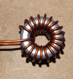
You've wound 18 turns on that core which will give you an inductance a bit higher than 10uH. Only 13 turns are needed for around 10uH according to some tests done by thomas using these cores and this gauge wire with another one of his amps. Winding more than 13 turns won't hurt anything, it will just lower the cutoff frequency and Q of the filter.
BWRX said:You've wound 18 turns on that core which will give you an inductance a bit higher than 10uH.
Thanks. That's why I'm not doing any soldering yet, I need to recover from Christmas first- I just assumed that your pictured example earlier in the thread was the correct way. Just stuck it on my DMM, and I'm getting 19uH, so maybe a little less than 13 turns is the way to go for 10uH.
For anyone else wondering, I found it easiest to start in the middle, and work back in both directions.
Great job Pinkmouse!! ... I'm suprised though, that you guys think winding coils is the tough job ... soldering them teeny, tiny caps to the board, now there's a challange. (Yeap, I count 18 turns too.)
I gotta get two other projects pushed aside on the bench first, then its off to the store to get another, bigger, better lamp / magnifier ... 🙄
I hope I can get something accomplished this week, like at least one current project done and outta the way ... 'cause:
I gotta go to CES in Las Vegas on the 8th ... always a serious chore ... so if you guys need anything, give me a shout and I'll see what I can do ... (some of the vendors there treat me like I know what I'm doing so sometimes I get freebees and discounts.)
😉
FastEddy said:Great job Pinkmouse!! ... I'm suprised though, that you guys think winding coils is the tough job ... soldering them teeny, tiny caps to the board, now there's a challange. (Yeap, I count 18 turns too.)
I gotta get two other projects pushed aside on the bench first, then its off to the store to get another, bigger, better lamp / magnifier ... 🙄
I hope I can get something accomplished this week, like at least one current project done and outta the way ... 'cause:
I gotta go to CES in Las Vegas on the 8th ... always a serious chore ... so if you guys need anything, give me a shout and I'll see what I can do ... (some of the vendors there treat me like I know what I'm doing so sometimes I get freebees and discounts.)
😉
I can solder surface mount stuff all day without any magnification and it doesn't bother me, but winding cores is a PITA. My hands always end up getting cramped and I have to take multiple breaks.
in concept, you can feedback the audio signal (post filter) to the input of the pwm generator as a means to introduce negative feedback.
the issue there I think is phase margin and stability issues associated with it.
I am going down a similar path, except that I am using a pwm controller (ucc2803) as a pwm generator to feed a half gate driver / mosfets. the pwm generator is working but the power stage not yet.
some of the pwm controllers have a good driver stage (the ucc2803 can drive 1amp). so it is possible to use them to directly drive a pair of n/p-channel mosfets. just some new ways to play with the devices.
" I can solder surface mount stuff all day without any magnification and it doesn't bother me, but winding cores is a PITA. My hands always end up getting cramped and I have to take multiple breaks. ..."
Lucky You!
Old man speaking: I can't do the close up stuff very well any more, but I can see that ant on that telephone pole across the street ... 🙄
Cramps? you think you got cramps ...
Lucky You!
Old man speaking: I can't do the close up stuff very well any more, but I can see that ant on that telephone pole across the street ... 🙄
Cramps? you think you got cramps ...
fokker: " ... you can feedback the audio signal (post filter) to the input of the pwm generator as a means to introduce negative feedback. ... the issue there I think is phase margin and stability issues associated with it. ..."
If you can come up with a picture or schematic, etc. for this please share it with us. (I know a guy who designed some very interesting Class-D amps that have no feed back loop at all = and it sound pretty good and runs cool ... I'll try to get his input.)
If you can come up with a picture or schematic, etc. for this please share it with us. (I know a guy who designed some very interesting Class-D amps that have no feed back loop at all = and it sound pretty good and runs cool ... I'll try to get his input.)
Package arrived today, thanks Brian. Now that I see the boards and the teeny weeny tiny components in real I'm getting second thoughts. 
That's 3 days ago, must have been some party!! 😉
Regards
That's why I'm not doing any soldering yet, I need to recover from Christmas first-
That's 3 days ago, must have been some party!! 😉
Regards
- Status
- Not open for further replies.
- Home
- Amplifiers
- Class D
- Texas Instruments TAS5261