-_nando-_ said:I just have a doubt, if the TPA2000 is a Filterless class D, does it put modulated PWMsignal out ?
For one, PWM (Pulse Width Modulation) is not digital. And you can trust me when I tell you that the TPA2000 will output dual (noninverted and inverted) PWM signals. If you don't believe me check out the data sheet just as I did.
I've made my own class d amps based on Tripath and MPS chips and have a reasonable grasp on the prinicples of operation and also PCB layout issues. As I said earlier, I have already started a layout of the TAS5261 output stage and will now include the TPA2000 mainly for evaluation purposes because it's a simple solution that doesn't require many parts. I will allow provisions for jumpering in PWM signals from some other source should someone want to use some other front end.
BWRX, I trust you ! 😉
I'm anxious to see your layout with TPA2000 and TAS5261, and for sure I'll try it.
Cheers
I'm anxious to see your layout with TPA2000 and TAS5261, and for sure I'll try it.
Cheers
BWRX said:
For one, PWM (Pulse Width Modulation) is not digital. And you can trust me when I tell you that the TPA2000 will output dual (noninverted and inverted) PWM signals. If you don't believe me check out the data sheet just as I did.
I've made my own class d amps based on Tripath and MPS chips and have a reasonable grasp on the prinicples of operation and also PCB layout issues. As I said earlier, I have already started a layout of the TAS5261 output stage and will now include the TPA2000 mainly for evaluation purposes because it's a simple solution that doesn't require many parts. I will allow provisions for jumpering in PWM signals from some other source should someone want to use some other front end.
Hi Brian,
it is true, PWM is not pure digital. But in the same sense are not pure digital:
* Pulse-code modulation (PCM)
* Pulse-amplitude modulation (PAM)
* Pulse-position modulation (PPM)
* Pulse-density modulation (PDM)
In the same sense a DAC make a conversion from analogue PCM to analogue sine wave, and from a CD-ROM come out analogue signals.
This way digital amplifiers don't exist, and all digital technology operates in the analogue realm.
Do we go back to usual sense of words?
PCM source -> PWM amp output = pure digital chain
PCM digital source -> Analogue DAC output -> Analogue PWM conversion -> PWM output = Digital/Analog/Digital conversions.
Of course I agree to start from bottom then go on.
Ciao
Thomas
thomaseliot said:it is true, PWM is not pure digital. But in the same sense are not pure digital:
* Pulse-code modulation (PCM)
* Pulse-amplitude modulation (PAM)
* Pulse-position modulation (PPM)
* Pulse-density modulation (PDM)
This way digital amplifiers don't exist, and all digital technology operates in the analogue realm.
Hi Thomas.
You're right that the meaning of digital can be argued over until the end of time, but it is good to know where digital ends and analog begins. I would agree with you that technically PCM, PAM, PPM, and PDM are not truly digital. However, while PWM is theoretically discrete in output level it is continuously variable in the time domain. Those other signals are theoretically discrete in both level and time. To me, that makes PWM a strictly analog signal, while the others are more of a digital analog signal, if you will.
Regardless, a digital representation of a signal is technically no longer digital once it given a timebase.
You did point out my mistake in the signal chain though.
It would either be:
PCM->DAC->PWM->Analog Output
or
PCM->PWM->Analog Output
BWRX said:I will allow provisions for jumpering in PWM signals from some other source should someone want to use some other front end.
Nice! Don't you think would be interesting to eliminate the DAC in the chain from CD transport or Hard disk to amp output?
The reason I'm not so enthusiast with TPA2000 is that already exist class d amps with separate driver and power stage. For instance the Tripath TC2000 provides PWM output from analogue input, and is used in 41HZ Amp2 and Amp4. TP2350 and TP2050 are their power stages, respectively. TP2350 is 300W 4ohm 0.03 THD+N and is the improved version of the chip used in Bel Canto Evo2 genII.
In any case I'm in if you make a board, I'm sure you will soon want to improve it 🙂.
Ciao
Thomas
thomaseliot said:Don't you think would be interesting to eliminate the DAC in the chain from CD transport or Hard disk to amp output?
It would certainly be interesting, but I'm not so sure that eliminating the DAC from the signal chain will actually lead to improved sonics at the current time. PCM>Analog>PWM sounds pretty darn good so far, although I haven't heard a PCM>PWM system yet.
The TPA2000 I suggested is a low power class d chip, but working into a very easy (and resistive) load will not give it any problems and will probably allow it to perform better with higher efficiency. Plus, it's bridged output stage conveniently provides the necessary PWM signals for the output stage. I'm sure TI didn't think it would ever be used for something like this 🙂
Thomas mentioned the Tripath PWM controllers and that is one of the other options I wanted to leave the door open for by having room to jump in signals from another board. It's best to think of this as an evaluation board and if one of us finds a good combo then it could be integrated onto a single board in the future. Simiplicity has its benefits; cost being being the one most of us have become familiar with.
As far as parts for the TAS5261 output stage go I've got some questions for everyone.
So far I've alloted space for two 18mm diameter 7.5mm lead spacing caps and one 8mm diameter 3.5mm lead spacing cap per half bridge. My plan was to use 1500uF 63V Panasonic FCs for the larger caps and 150uF 63V Panasonic FMs for the smaller cap. Of course any cap with at least a 63V rating, the proper lead spacing, and diameter could be used.
What is the consensus regarding the output inductors? TI appears to have used a T106 size toroid core on their evaluation board. The core is fully wound with a single layer winding and the wire looks to be about 16 gauge. Anybody care to source some good ones for this application?
I do have T106 toroids for sale. $10 a piece. It was purchased for similar applications, up to 300W. Supply is limited. Please email if interested.
I've used these with Tripath TA2022. Do you remember the coils with the rope here?
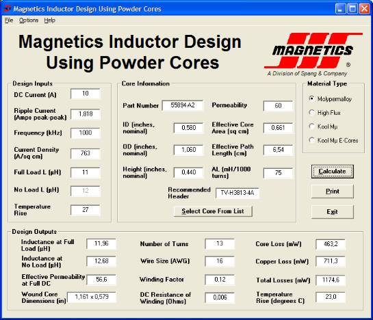
These sound better. 106 OD Molypermalloy: only 13 turns 16AWG for 11uH.
I bought them online in small quantities, together with wire from CWS: www.coilws.com. They cost 3$ each.
The software to calculate coils is here
These sound better. 106 OD Molypermalloy: only 13 turns 16AWG for 11uH.
I bought them online in small quantities, together with wire from CWS: www.coilws.com. They cost 3$ each.
The software to calculate coils is here
Thomaseliot,
So these cores sound better than the Bertus cores - is that right?
Can you say in what way?
John
So these cores sound better than the Bertus cores - is that right?
Can you say in what way?
John
Wich way?
Clarity almost, and better timber fidelity of instruments. If T80 ferrite is 100, bertus coils are 180 and MPP 200. But transients are impressive with MPP much more. Sound of (acoustic) Piano is far improved: each "hit" is real and resonances of each note are well tuned and remain in the air while shading.
Clarity almost, and better timber fidelity of instruments. If T80 ferrite is 100, bertus coils are 180 and MPP 200. But transients are impressive with MPP much more. Sound of (acoustic) Piano is far improved: each "hit" is real and resonances of each note are well tuned and remain in the air while shading.
I've finished laying out the power and output sections and should be able to fit everything (including the TPA2000D1 and supporting circuitry - supply regulators, etc.) nicely on a 100mm x 78mm double sided pcb. TIs evaluation board is 115mm x 174mm so this will be considerably more compact. There is space for 4 large electrolytics, 2 smaller electrolytics, and 2 ceramic bypass caps on the power rails. There are provisions for supply rail snubbers and output snubbers. There's plenty of room for T106 or slightly larger toroids, 5mm or 7.5mm lead spacing film output caps, and an 8 position 3.5mm lead spacing terminal block for power, ground, and output connections.
I plan on using npn transistors with a zener reference to come up with the 12V gate drive supplies from the 50V rail and will do something similar for the 3.3V supplies needed for the TPA2000D1. Chip regulators could be used instead, and I was thinking of doing this for the deriving the 3.3V supplies from the 12V rails so the TPA2000D1 has some nice filtered and stable power.
Here's a sneak peek at the layout. The image is very close to the board's actual size.
Attachments
Hi,
looks like very simple. But it is the art of design.
I've just two 106 MPP toroids left 😀 . Is there space for 16AWG wire?
http://www.diyaudio.com/forums/showthread.php?postid=1026147#post1026147
Isn't it usually better to use two separate regulated PS with small transformers for 3.3V and 12V?
looks like very simple. But it is the art of design.
I've just two 106 MPP toroids left 😀 . Is there space for 16AWG wire?
http://www.diyaudio.com/forums/showthread.php?postid=1026147#post1026147
Isn't it usually better to use two separate regulated PS with small transformers for 3.3V and 12V?
It looks simple because everything is built into the chips 🙂
16ga wire on T106 cores will fit fine. There should be room for thicker wire if you'd want to go that route. What's the outer diameter of 14 and 16ga magnet wire?
It would be better to use separate small transformers to derive the 12V and 3.3V rails, but that's another transformer you'd need to buy. The cost of components needed to derive the 12V and 3.3V rails from the 50V rail will be cheaper than a transformer, bridge rectifiers, smoothing caps, and regulators. I will leave space to jumper in an external 12V and 3.3V supply if anyone wants that option.
Hi,
jumper solution is nice, we would add separate supply only if it is worth.
What about two jumpers to switch to PWM input from an external TAS5518? 🙄
I'm reading TAS5518 hundred and three pages. This too would be quite easy to design, but a microcontroller is needed to control volume, input data format and many other things.
I got a usb->i2s converter and a PIC programmer to start learning. 😀
Oh I'm so happy to see the board borning ! 😀
I think that the zenner + transistor is better than the regulator solution, a bit more unstable, but less noisy... Am I right? It's based in little experience, not enough to be sure
Very nice, what is the most cool in this board, is that you're leaving some jumper options to drive the power stage with an external pwm modulator and also the regulated voltage (3.3 and 12v) from a external supply, very flexible indeed ! 😉
Cheers,
Fernando
The problem I've run into is what load to use at the outputs of the TPA2000D1. We don't want it waste too much power, so something like 16ohms or more would be good. Plus, the more current that draws the beefier the 12V regulators will have to be. A good bit of heat will be wasted in the SOT223 transistors to go from 50V to 12V at any appreciable amount of current. Then again, I plan on using separate transistors for each 12V supply for better regulation and less heat dissipation in each one. Same goes for the 3.3V supplies for the TPA2000.
And according to that table, 16ga is the largest diameter wire that will fit the through holes I've used. I can make them bigger if anyone thinks that would be beneficial.
I already said I'd include those 🙂thomaseliot said:What about two jumpers to switch to PWM input from an external TAS5518?
And according to that table, 16ga is the largest diameter wire that will fit the through holes I've used. I can make them bigger if anyone thinks that would be beneficial.
Upon further consideration, I've decided that it will be better to derive the 12V gate supplies from the 50V rail. An external 12V supply will then be required for the other 12V Vdd pin of the TAS5261. I'll probably leave space on the board for a simple 3 terminal regulator so an external unregulated supply may be used. The 3.3V supply for the TPA2000 will also be derived from the external 12V supply in order to keep the input stage supplies separated from the output stage supplies as much as possible.
Any feedback or suggestions are certainly welcome. Especially from those of you who will be interested in one of these boards.
Any feedback or suggestions are certainly welcome. Especially from those of you who will be interested in one of these boards.
- Status
- Not open for further replies.
- Home
- Amplifiers
- Class D
- Texas Instruments TAS5261