Hi all.
I have a vintage Texan Amplifier of '70s fame and have just rebuilt the power stage (again!) with TIP 41C and TIP 42C power transistors.
Arrgh Its all gone horribly wrong!
Anyway, - minor explosion caused failure of power devices, assorted fuses and toroidal transformer supply.
Have got around power prob by using alternative tappings (+ and - 25V) and have replaced power transistors with TIP 41 and 42 Cs which I've had since last rebuild.
Getting close to resolution but cannot understand current level of quiescent current. I have a 250 ma ammeter and it goes off the scale on both channels. No sign of damage on power devices and all other factors seem in order. changing values of variable resistors makes no difference.
I'm sure one of you guys will spot it, - alternatively, just writing out the problem often causes a solution to drop!
Thanks again
Martin
Very good point JonSnell,
Well spotted!
M
An externally hosted image should be here but it was not working when we last tested it.
Well spotted!
M
Is TR1 OK? RV24 and R25? There is no current sensing resistors in the output stage, the second version has these added but in the collectors not emitters. Where are you placing your ammeter? With RV24 at minimum resistance the quiescent current should be very low, increasing the resistance will increase the quiescent current. Check with a 60Watt incandescent lamp in series with the mains to limit the current.
This might be one of those cases where the power stage is best rebuilt from scratch. CFP output stage with gain, biasing that isn't inherently failsafe, no Miller cap on BC212, no emitter resistors... Anything wrong with putting in an ordinary LM3886?
Yes, it won't be the same amplifier.This might be one of those cases where the power stage is best rebuilt from scratch. CFP output stage with gain, biasing that isn't inherently failsafe, no Miller cap on BC212, no emitter resistors... Anything wrong with putting in an ordinary LM3886?
It was a cool design for its day - low profile, compact etc.
It would be an interesting project to redo it using modern components - but I'd not go for the CFP OPS.
Maybe we could call it the 'Arizona 30+30'.
Replace all those 741's with NE5532/34 etc.
I worked on one around 1980 IIRC - nice little amp 🙂
It would be an interesting project to redo it using modern components - but I'd not go for the CFP OPS.
Maybe we could call it the 'Arizona 30+30'.
Replace all those 741's with NE5532/34 etc.
I worked on one around 1980 IIRC - nice little amp 🙂
Latest progress is that isolating the various components of the power stage makes no difference! (See schematic), alternately lifting a leg of R26 ad R27, then R126 and R127 makes no difference, the remaining channel still seems to take nearly an amp. Anybody got any ideas as to where this energy is going since it is not cooking any of the board components?
https://www.google.co.uk/search?q=te...W-vT4GFasfM:
https://www.google.co.uk/search?q=te...W-vT4GFasfM:
It was a cool design for its day - low profile, compact etc.
It would be an interesting project to redo it using modern
components - but I'd not go for the CFP OPS.
Hi,
It has been done, Rega reworked the Texan for the original
Brio clamshell amplifier design. I bought one used for a friend.
Your quite wrong about the CFP OPS, it is mandatory in
this case to add additional voltage gain, the whole point.
If not a CFP OPS then you cannot use an op-amp as
an input to a power amplifier, in any simple sense.
rgds, sreten.
Schematics for the Brio 1 can be found online if you search.
Last edited:
Fit a bulb limiter to the mains supply, photocopy or print out the schematic, then power up with the limiter in place and measure the voltages at each transistor lead in the output stage and those of the differential inputs and output of the ICs too, with respect to ground. Write them on the schematic and compare them to the other channel. Post here if the painful truth doesn't become obvious first.
Don't fit speakers or apply any signal for testing DC conditions. 'No need to make matters worse or confused by AC.
Don't fit speakers or apply any signal for testing DC conditions. 'No need to make matters worse or confused by AC.
Hi,
It has been done, Rega reworked the Texan for the original
Brio clamshell amplifier design. I bought one used for a friend.
Your quite wrong about the CFP OPS, it is mandatory in
this case to add additional voltage gain, the whole point.
If not a CFP OPS then you cannot use an op-amp as
an input to a power amplifier, in any simple sense.
rgds, sreten.
Schematics for the Brio 1 can be found online if you search.
Naah.
I can think of two or three ways to retain the op-amp front end and use an EF OPS. You have plenty of loop gain with the op amp anyway. I would say the low supply voltages would be a problem with the EF because you'd lose 2-3V peak - but easy enough to raise them a few volts.
However, this is the Texan thread so I'll stop hijacking it - apologies to the OP and good luck with your amp!
🙂
The Texan issue was not loop gain but mainly slew rate plus output swing.Bonsai said:You have plenty of loop gain with the op amp anyway.
I too have a Texan (original version), although not used for a while.
Response to suggested remedy
Many thanks to Ian Finch. Will follow his advice and get back in a day or so...
Many thanks to Ian Finch. Will follow his advice and get back in a day or so...
Is the excessive current drawn with the bottom cover in place? This can short PCB contacts if these are too long.
Bottom Plate
Thanks to Paul Kemble for a sensible suggestion but the plate concerned is already removed and the board is in the naughty naked nude!
Thanks to Paul Kemble for a sensible suggestion but the plate concerned is already removed and the board is in the naughty naked nude!
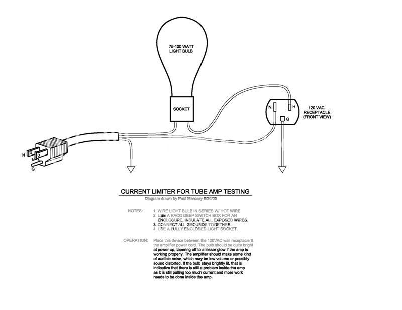
Did you find enough detail to rig up a bulb limiter/tester ? (safely, that is) 🙂
Here's a simple wiring diagram and directions that will be compatible with most earthed mains supplies, if you aren't certain. Try a 40-60W globe for a small amp like the Texan. Note that all the wiring and sockets should be housed in an insulated case like an electrical wiring box, jiffy box etc. No one wants to electrocute the kids or pets with loose or unshielded wiring:
Here's a simple wiring diagram and directions that will be compatible with most earthed mains supplies, if you aren't certain. Try a 40-60W globe for a small amp like the Texan. Note that all the wiring and sockets should be housed in an insulated case like an electrical wiring box, jiffy box etc. No one wants to electrocute the kids or pets with loose or unshielded wiring:
Naah.
I can think of two or three ways to retain the op-amp front end and use an EF OPS. You have plenty of loop gain with the op amp anyway. I would say the low supply voltages would be a problem with the EF because you'd lose 2-3V peak - but easy enough to raise them a few volts.
However, this is the Texan thread so I'll stop hijacking it - apologies to the OP and good luck with your amp!
🙂
Hi,
Loop gain is not the issue. The CFP OPS is configured with
voltage gain as well as current gain, so the op-amp output
voltage swing can drive the OPS rail to rail. There is no simple
easy way to drive a unity gain EF OPS for this configuration.
Its what makes it a Texan : op-amp + CFP OPS with gain.
rgds, sreten.
- Status
- Not open for further replies.
- Home
- Amplifiers
- Solid State
- Texan Rebuild