Hi,
Earlier you said both channels have excessive bias, whilst it
seems its clearly its not the same problem in both channels.
It should not be possible a working TR2 has 2.5V across b-e.
rgds, sreten.
Earlier you said both channels have excessive bias, whilst it
seems its clearly its not the same problem in both channels.
It should not be possible a working TR2 has 2.5V across b-e.
rgds, sreten.
Great to have you guys on the case.
A couple of points of clarification. The meter I'm using is analog - a "Smart" meter from way back, Volt, Ohms, Amps etc.
I have measured the voltages in question directly, channel 1 gives base - emitter Tr2 of 0.5 volt, channel 101 gives base - emitter Tr2 (102) of 2.5 volt.
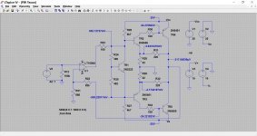
Mooly's simulation is interesting, the value for R29 should be 22 not 220. Lets see what we get when I open circuit Tr2 and measure the emitter voltage...
ML
His simulation suggests the base emitter junction has gone open circuit and you will have to replace Tr2.
While you are cross referencing voltages from the channel that is working I suggest you look at Tr1 and its' network. You have 5 volts between the driver transistors bases in the faulty channel what is the reading in the working channel.
Last edited:
Further clarification:
Neither channel has yet been found to work. All that has happened is that I have tested the current going thru the positive rail and found it well in excess of the 30 odd mA recommended, - its nearer an amp!
Its at this point that I've asked for help from you guys, and Ian Finch suggested the voltage measurements taken above.
Whilst I am sure what is said about the B - E voltage being accurate for a working circuit, that is not what this is. I am sure its defective but so far do not know in what way. I have replaced the seemingly faulty device, Tr2 (102) but this has made no difference.
ML
I'm not familiar with that one but the question is really about the meter's resolution. What is the lowest voltage range you can use?....The meter I'm using is analog - a "Smart" meter from way back, Volt, Ohms, Amps etc....
Perhaps the bulb limiter confuses some who don't use them and are looking for voltages such as when there are shorts and high current flowing. Is the bulb flashing at least on power up? If the bulb is fitted but not glowing and the rail voltages remain steady at 25V though, there can't be a lot of current flowing there. What is different now from when there was more like an amp of current flowing? Just the limiter? Replaced TR2?
Further clarification:
Neither channel has yet been found to work. All that has happened is that I have tested the current going thru the positive rail and found it well in excess of the 30 odd mA recommended, - its nearer an amp!
Its at this point that I've asked for help from you guys, and Ian Finch suggested the voltage measurements taken above.
Whilst I am sure what is said about the B - E voltage being accurate for a working circuit, that is not what this is. I am sure its defective but so far do not know in what way. I have replaced the seemingly faulty device, Tr2 (102) but this has made no difference.
ML
In post 32 you were asked to give some voltage readings which would help us to home in on problems. There is still a blank in this regard.
The voltage between the driver transistor bases in the circuit attachment was 1.34 volts. If your hardware measures in excess of that and is not adjustable you have to consider whether this is consequent to a problem elsewhere or is this the cause of the problem.
Consider accordingly, figure 4 in datasheet http://www.onsemi.com/pub_link/Collateral/2N5550-D.PDF 2N5550/5551 - at 0.9 volts across the base emitter for either of these devices is capable of conducting 100 m.a. The conduction curve is on an upward slope at this point running off the graph.
A couple of points of clarification. The meter I'm using is analog - a "Smart" meter from way back, Volt, Ohms, Amps etc.
Its very important that you first of all confirm that the meter follows modern practice of having the red lead as positive when performing resistance checks. You need to know that in order to be able to tell whether a transistor is NPN or PNP when tested.
I have measured the voltages in question directly, channel 1 gives base - emitter Tr2 of 0.5 volt, channel 101 gives base - emitter Tr2 (102) of 2.5 volt.ML
Providing that the base is the more positive of the two, then that is absolute conclusive proof of a problem around that transistor. It could be faulty. It could be something other than it appears to be such as a fake, and this is why you need to be able to prove by measurement that it really is NPN by knowing your meter polarity on ohms ranges. It may even have a different pin out to what you are expecting and what is the industry standard for that device. That can actually happen.
Mooly's simulation is interesting, the value for R29 should be 22 not 220. Lets see what we get when I open circuit Tr2 and measure the emitter voltage...ML
I never spotted that slip up despite several minutes working on it all and switching screens around 😱
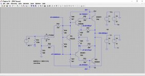
I've reposted the voltage measurements with that corrected and the bias set for 30ma in the output devices.
Hi,
Earlier you said both channels have excessive bias, whilst it
seems its clearly its not the same problem in both channels.
It should not be possible a working TR2 has 2.5V across b-e.
rgds, sreten.
This is the crux of it all. Whatever other problems the amp may or may not have, 2.5 volts across a forward biased junction isn't possible.
Whilst I am sure what is said about the B - E voltage being accurate for a working circuit, that is not what this is. I am sure its defective but so far do not know in what way. I have replaced the seemingly faulty device, Tr2 (102) but this has made no difference.ML
No matter what problems a circuit has, something such as this B-E voltage is determined by the physical properties of silicon transistors. In other words a problem elsewhere can not change that voltage above this 0.7 figure. You could see lower voltage (less than 0.7) and you could see a reverse voltage higher than 0.7. Reverse voltage means that for the NPN device such as this, the emitter would be measuring as the more positive of the two.
In post 32 you were asked to give some voltage readings which would help us to home in on problems. There is still a blank in this regard.
The voltage between the driver transistor bases in the circuit attachment was 1.34 volts. If your hardware measures in excess of that and is not adjustable you have to consider whether this is consequent to a problem elsewhere or is this the cause of the problem.
Seeing them written in on the simulation would possibly help. Its much easier to assimilate it all that way.
Attachments
@Martin
BC182 and BC212 seem to be discontinued product and the question arises if some of these have needed to be replaced what were the substitute types. These particular items have a lead configuration order - of collector - base - emitter when reading the front face. With 2N types the order is in reverse. Can you confirm if any 2N substitutions have been made the lead orientation is correct relative to the board.
BC182 and BC212 seem to be discontinued product and the question arises if some of these have needed to be replaced what were the substitute types. These particular items have a lead configuration order - of collector - base - emitter when reading the front face. With 2N types the order is in reverse. Can you confirm if any 2N substitutions have been made the lead orientation is correct relative to the board.
Answers to the above, in no particular order
44, - The meter has 4 voltage ranges, 500V, 125V, 25V and 5V. Measurements taken wth 5V range except where this is exceeded.
So far the bulb has flashed once at power up, - this was in a condition of lower ambient light, so poss its just not being noticed otherwise.
As far as I can see there's no difference except I'm happy none of the devices are cooking. Tr2 has been replaced but no difference noted.
45 - I have the amended circuit image in hand and will post shortly.
46 - Red lead is positive. Will test transistor to check NPN or PNP and post.
47 - Substituted device has BC 182 marked on it, will check the pinout.
Thanks again guys, - well get there!
45 - I have the amended circuit image in hand and will post shortly.
That's what we need 🙂
46 - Red lead is positive. Will test transistor to check NPN or PNP and post.
Although I wouldn't normally recommend this, you could swap the suspect device with that from the other channel. Lets keep that as a last resort.
---------------------------------------------------------------
So for the BC182, and with your meter having the modern configuration of red being positive for ohm ranges, you should read similar to a forward biased diode if you place the red lead on the base and black lead on the emitter. Keeping the red on the base and transferring the black to the collector should read similarly. If you reverse the leads (so now black on base) you should get a reading of infinity (no deflection).
Attachments
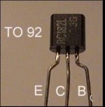
Erm....that pinout will be CBE for later Texas, Fairchild and Multicomp TO92 transistors at least, in the BC18X/BC21X series. Some Motorola product was known to be reversed to EBC when they produced them too, but they used different Jedec codes like TO226AA to specify their outlines and their pinouts with style codes. http://www.onsemi.com/pub_link/Collateral/BC182-D.PDF
BTW, Multicomp replacements for BC182B (Farnell, so could be any origin) which are available, have a minimum Hfe spec. like a power transistor - woeful.
BTW, Multicomp replacements for BC182B (Farnell, so could be any origin) which are available, have a minimum Hfe spec. like a power transistor - woeful.
Last edited:
I have four devices marked "BC182". These include the one removed and replaced. With the red lead on the base, black to emitter and black to collector reads infinity. With the
black lead on the base, red to emitter and red to collector reads C.200 ohms each
ML
black lead on the base, red to emitter and red to collector reads C.200 ohms each
ML
Beware the "F" logo. Most Online product is clearly dodgy (wrong logo and shaky laser etching) BC182 NPN Transistors TO 92 BC182C 100PCS-in Transistors from Electronic Components & Supplies on Aliexpress.com | Alibaba Group
None of this means the devices are necessarily defective. They have passed all tests suggested. Need to look elsewhere.
ML
ML
46 - Red lead is positive. Will test transistor to check NPN or PNP and post.
I'm taking you at your word on this 🙂 Most analogue meters actually have reversed polarity on ohms ranges.
I have four devices marked "BC182". These include the one removed and replaced. With the red lead on the base, black to emitter and black to collector reads infinity. With the
black lead on the base, red to emitter and red to collector reads C.200 ohms each
ML
So your measured result does not compute. If the meter is as you say then you have a PNP device in your hand, not an NPN.
We're not trying to trip you up with this... its a basic fundamental that we have to be absolutely sure on.
Do you have any spare TIP 41 or TIP42 that you can double check the meter with ?
I agree, it looks wrong. Have tested the meter by attaching leads to a dry cell, - reads 1.3 volts, red is on positive terminal. Have spare TIP transistors so will check and get back.
Have tested with TIP 42C. Red lead on base gives 200 ohms with black on emitter and 200 ohms with black on collector. Black lead on base gives infinity with red on emitter and red on collector.
Which proves what?
ML
Which proves what?
ML
Your TIP42 test (which is a PNP) proves your meter has 'reversed polarity' on the ohms ranges (which is actually normal for most analogue meters). The transistor junctions for this device are conducting correctly when the base is negative with respect to the emitter or collector.
It takes a bit of mental juggling when using an analogue meter for this 😉
If you did the same test with a DVM then you would find the black lead would need to be on the base... the opposite of yours.
On ALL other meter ranges that are polarity conscious (so that is DC volts and DC current) your meter will be correct in that red is positive and black is negative.
So lets go back to your BC182 where you said:
So knowing now that your meter is reversed on ohms ranges, we can say that these appear to be identified correctly as NPN's
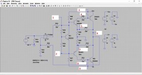
Where next... we mustn't lose sight of this 2.5 volts you seem to be getting across the base/emitter junction of TR2. I've marked all the relevant voltages points as numbers 1 through to 9 on the diagram below.
If you can measure and report the voltages you have at each point, I'll insert them onto the diagram and we'll see if it makes any sense. I've marked the supplies to be measured as well.
You will see that voltage '1' and voltage '5' are the B and E of TR2. So can you also measure again the voltage you are seeing across TR2 B and E. It should of course be the same as voltage '5' subtracted from voltage '1' but lets do a double proof and make sure that it is. To measure this voltage place the RED lead on the base and the BLACK on the emitter and record the measured voltage as PLUS or MINUS 'xyz'. If the meter deflects the wrong way when connected as described then the voltage is NEGATIVE 'xyz'
Its quite an interesting puzzle at the moment 🙂
It takes a bit of mental juggling when using an analogue meter for this 😉
If you did the same test with a DVM then you would find the black lead would need to be on the base... the opposite of yours.
On ALL other meter ranges that are polarity conscious (so that is DC volts and DC current) your meter will be correct in that red is positive and black is negative.
So lets go back to your BC182 where you said:
I have four devices marked "BC182". These include the one removed and replaced. With the red lead on the base, black to emitter and black to collector reads infinity. With the black lead on the base, red to emitter and red to collector reads C.200 ohms each
So knowing now that your meter is reversed on ohms ranges, we can say that these appear to be identified correctly as NPN's
Where next... we mustn't lose sight of this 2.5 volts you seem to be getting across the base/emitter junction of TR2. I've marked all the relevant voltages points as numbers 1 through to 9 on the diagram below.
If you can measure and report the voltages you have at each point, I'll insert them onto the diagram and we'll see if it makes any sense. I've marked the supplies to be measured as well.
You will see that voltage '1' and voltage '5' are the B and E of TR2. So can you also measure again the voltage you are seeing across TR2 B and E. It should of course be the same as voltage '5' subtracted from voltage '1' but lets do a double proof and make sure that it is. To measure this voltage place the RED lead on the base and the BLACK on the emitter and record the measured voltage as PLUS or MINUS 'xyz'. If the meter deflects the wrong way when connected as described then the voltage is NEGATIVE 'xyz'
Its quite an interesting puzzle at the moment 🙂
Attachments
Hi,
Its frustrating listening to someone complaining their amplifier
doesn't work, who can't be bothered to work out how it should
work, and use that information to work out the actual problem.
As a student on placement I fixed a broken power supply for a
laser that had for years baffled all the laser companies service
personnel. It was an enigmatic "unfixable" box in the lab corner.
Apparently every service engineer had tried and failed to fix it.
At a lull in demand for fixing stuff I had a go at it.
How and why ? Because they thought all you needed to do is find
and fix the broken parts. However I ascertained that it simply
wasn't doing what it was supposed to do, in a section of the
circuit, and in fact had been poorly modified by the customer,
so it could never work with just new parts thrown at it.
Reversing the modification was trivial, and then it worked just fine.
Point is, understand how what you are trying to fix should work.
Its a massive bonus in making sense of what your measuring.
rgds, sreten.
Last edited:
You have the fullest explanation from Mooly on Analogue meters. I was about to reply since I still use one for certain tests. He has made a better job of it than I would have.
If you want the simplest of rules, another way to think of an analogue meter is that the battery is only used for resistance readings and the battery positive is connected to the black lead terminal.
Here are some out of circuit tests you can put to good use with your meter
- for both NPN and PNP types there should be a high resistance reading across the collector to emitter pins no matter which way you apply the leads. This is known as the "Punch Through" test - proving there is no short circuit.
For the remaining junction tests with NPN transistors the black lead needs to be applied to the base. For PNP it is the red.
In either case when the alternative lead is in contact to the collector or the emitter, the resistance reading should be low.
This will confirm that the respective junctions are not open circuit.
If the leads are applied the wrong way round and a low reading results then there is a short circuit in the junction being tested.
Can you try these tests on transistors you have removed and share the outcomes.
whe
- Status
- Not open for further replies.
- Home
- Amplifiers
- Solid State
- Texan Rebuild