Ian
Thanks again for the sound advice. Have just finished strapping together a device that looks reassuringly like yr diagram. Will progress getting the data over the next day or so and post.
Best
ML
Thanks again for the sound advice. Have just finished strapping together a device that looks reassuringly like yr diagram. Will progress getting the data over the next day or so and post.
Best
ML
Texan Current Problem
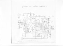
Have followed Ian Finch's sound advice and measured voltages around both channels with current limiter in circuit.
Results are attached, if anybody can deduce from this why the positive rail current should be in excess of 250mA (quiescent) then your help would be much appreciated.
ML
Have followed Ian Finch's sound advice and measured voltages around both channels with current limiter in circuit.
Results are attached, if anybody can deduce from this why the positive rail current should be in excess of 250mA (quiescent) then your help would be much appreciated.
ML
Attachments

Good effort. Perhaps other's who've built or worked on one will have some idea of the setup procedure and what is likely to have caused the lack of bias adjustment. Check Vbes a bit closer, as advised.
Right hand picture, TR2. NPN (BC182). 2.5 volts on the base, zero on the emitter = answers on a postcard please 🙂
(clue... the B-E junction when forward biased should be similar to silicon diode in it volts drop)
(clue... the B-E junction when forward biased should be similar to silicon diode in it volts drop)
Hi,
What Mooly is alluding to is all base emitters junctions
when conducting will be in the 0.5V to 0.7V range, the
forward drop of a diode, without exception.
Personally I'd download the free TinaTi simulator and
model the output stage and op-amp drive. Simulated
voltages should be very near the measure values.
SPICE-Based Analog Simulation Program - TINA-TI - TI Software Folder
rgds, sreten.
Guys
Whilst your kind advice is much appreciated, I'm still no further forward. Having replaced and tested Tr2 (102) it has made no difference to the 2.5 volt value, and the removed transistor checks out like two working back to back diodes.
Am I missing something ?
Thanks again
ML
Whilst your kind advice is much appreciated, I'm still no further forward. Having replaced and tested Tr2 (102) it has made no difference to the 2.5 volt value, and the removed transistor checks out like two working back to back diodes.
Am I missing something ?
Thanks again
ML
Are you reading this voltage of 2.5 across B and E or are you deducing it from two separate voltage readings, one to the base, one to the emitter, and then subtracting the two.
The first method is the only valid one.
The first method is the only valid one.
Guys
Whilst your kind advice is much appreciated, I'm still no further forward. Having replaced and tested Tr2 (102) it has made no difference to the 2.5 volt value, and the removed transistor checks out like two working back to back diodes.
Am I missing something ?
Thanks again
ML
Have a close look at the colour band on your R31 to make sure it is 4k7 and not 47k. Measure the resistance if unclear.
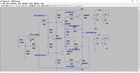
This shows the typical DC voltages and highlights the magic 600 to 700mv B-E voltage for a forward biased junction.
Martin... if you copy the image and replace all the marked voltages with your measured DC voltages then we might get more of a clue.
If you say you have replaced this problem transistor and you are still seeing 2.5v across B and E then I suspect that the device either has different pinouts to the original or its a fake (PNP instead of NPN) You can easily check that by checking the with your RED meter lead on the base, that you then are able to read the 'two diodes'. One to emitter and one to the collector. The base is the common point, red lead on the base for an NPN.
Attachments
As per Ian Finch's advice, all measurements are take with respect to earth, ie amp's metal chassis. This gives a base to emitter voltage of 2.5V since the emitter is measured at zero (see diagram)
Your kind attention is appreciated.
ML
Your kind attention is appreciated.
ML
I asked the OP to make a simple set of measurements with a bulb limiter in place, just measuring all points with respect to ground. There will be some interpretation errors but I think he is using an analog meter or a low resolution digital. (Is that right, Martin?) Accuracy could be poor this way too but still not bad enough to affect V B-E to the tune of 2V on any BJT.Are you reading this voltage of 2.5 across B and E or are you deducing it from two separate voltage readings, one to the base, one to the emitter, and then subtracting the two.
The first method is the only valid one.
The next logical step was to go around checking abnormal B-E voltages directly as you say Mooly, but 2.5V, if real, does mean bin time. If you recheck the V B-E (or rather Vbe) out of circuit it won't be 2.5V. If the transistor is alive, it's always one diode drop or ~ 0.7V, as others have said.
Interesting that with zero voltage everywhere that I'd expect some small current to be flowing, the quiescent current must be then be zero too or the meter range is set too high to read it.
The reason I say to always check directly on the device is three fold.
Firstly, in the time it takes to make two measurements, circuit conditions (thermal drift) and even the mains voltage may have changed all of which can affect the results.
Secondly, impedance of the circuit matters (and more so if using a cheap low sensitivity analogue meter). The meter resistance itself can upset biasing and give inaccurate results in some cases.
Thirdly, you can get odd readings if for example the print was open circuit somewhere and one of the leads transistor was effectively floating. Placing a meter lead on that point could cause all sorts of weird effects and again give a meaningless result.
And related to this... I assumed the meter would be DVM. Now some analogue meters (AVO8 for example) have the red lead as 'negative' when performing resistance checks compared to the DVM's more conventional red equals positive. This means that diodes conduct when the red lead is placed on the striped end, compared to the DVM where the black lead has to be on the striped end.
So in order to determine if a device is NPN or PNP you have to know your meter. So check a known good device (say a diode) and make sure the meter reads as expected.
Interesting that with zero voltage everywhere that I'd expect some small current to be flowing, the quiescent current must be then be zero too or the meter range is set too high to read it.
Hi Ian,
If we open circuit TR2 B-E in the simulation then we get fairly similar voltages to those I think Martin is describing.
Attachments
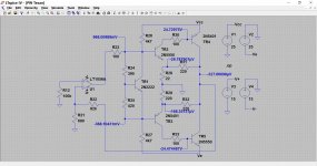
According to the measurements there is a voltage drop of 5 across TR1. That is an excessive amount and you will need to find out why. That would lead to high standing current in the output stage and consequent failures. Possibly that part is faulty or there is a problem with the network around.
Last edited:
Great to have you guys on the case.
A couple of points of clarification. The meter I'm using is analog - a "Smart" meter from way back, Volt, Ohms, Amps etc.
I have measured the voltages in question directly, channel 1 gives base - emitter Tr2 of 0.5 volt, channel 101 gives base - emitter Tr2 (102) of 2.5 volt.
Mooly's simulation is interesting, the value for R29 should be 22 not 220. Lets see what we get when I open circuit Tr2 and measure the emitter voltage...
ML
Re R26, - have checked the colour bands, - yellow, violet, red gives 4.7k, which is confirmed by measurement with the meter.
ML
ML
- Status
- Not open for further replies.
- Home
- Amplifiers
- Solid State
- Texan Rebuild