I think its now well established that the analog meter reads NPN and PNP devices backwards. Reference to posts 57 and 58 shows use against a known NPN and comparison with the BC 182 in question.
Base to Emitter measurement of Tr2 (102) gives 2.5 volts.
Please find attached diagram with requested voltages filled in. RV 24 is missing.
Prob does seem strangely intractable.
ML
Base to Emitter measurement of Tr2 (102) gives 2.5 volts.
Please find attached diagram with requested voltages filled in. RV 24 is missing.
Prob does seem strangely intractable.
ML
Attachments

The removed BC 182 gives high resistance across the collector - emitter, gives 250 ohms
black lead to base, red to collector and emitter, infinity with red lead to base.
ML
black lead to base, red to collector and emitter, infinity with red lead to base.
ML
The removed BC 182 gives high resistance across the collector - emitter, gives 250 ohms
black lead to base, red to collector and emitter, infinity with red lead to base.
ML
That would be Tr2 which would have been OK.
Current flows from emitter to collector in a NPN transistor and there is a path from earth to Tr2 emitter and a voltage of 2.5 via R26 at the base. This will turn Tr2 hard on and Tr4 as well.
Similarly the NPN Tr1 is to act as a path to draw some current from the negative rail via R27 - something is amiss here.
You should check the resistors on the negative rail side are intact.
You can test related transistors in circuit there by Mooly's method. The base to emitter difference should be c 0.6 volts +/- appropriate to polarity.
You can test for overheating parts by feeling for drafts around them by moistened finger.
P.S. to Post 61
Have also tested Channel 1 with Tr2 Emitter disconnected (open circuit, see previous posts).
Base voltage of Tr2 around 10 volts! - suspect different problem.
ML
Have also tested Channel 1 with Tr2 Emitter disconnected (open circuit, see previous posts).
Base voltage of Tr2 around 10 volts! - suspect different problem.
ML
P.S. to Post 61
Have also tested Channel 1 with Tr2 Emitter disconnected (open circuit, see previous posts).
Base voltage of Tr2 around 10 volts! - suspect different problem.
ML
You need to quantify by measuring - and making a list of voltage drops across all resistors and Vbe's of all transistors. Come back with these and some thoughts that others can look at.
Last edited:
Thanks for the voltages... interesting 🙂
On the BC182. A resistance check between collector and emitter (black lead on collector and red on emitter) should show infinity. Use the 'highest' ohms range on the meter (the range that measures resistors in the meg ohm region) and the reading should still be infinity.
We still must concentrate on this 2.5 volts B-E voltage. If the transistor is good, then this condition isn't possible under static DC conditions. So that leads on to another thought... is the amp actually 'OK' in a basic sense, but unstable and oscillating at high frequency. I'm guessing you haven't a 'scope to check on this.
Oscillation can give misleading DC readings because the meter can not interpret what is going on and so can in some cases give totally inaccurate results.
(Has the opamp ever been replaced for something different ?)
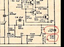
Two things to look at.
1/ Check that the two components marked below are OK, particularly the resistor.
2/ We can 'force' the bias to zero as a test by shorting out the vbe multiplier. That wont necessarily stop oscillation (if that is occurring) but it should bring the bias current down and as such is a good clue as to what is going on.
On the BC182. A resistance check between collector and emitter (black lead on collector and red on emitter) should show infinity. Use the 'highest' ohms range on the meter (the range that measures resistors in the meg ohm region) and the reading should still be infinity.
We still must concentrate on this 2.5 volts B-E voltage. If the transistor is good, then this condition isn't possible under static DC conditions. So that leads on to another thought... is the amp actually 'OK' in a basic sense, but unstable and oscillating at high frequency. I'm guessing you haven't a 'scope to check on this.
Oscillation can give misleading DC readings because the meter can not interpret what is going on and so can in some cases give totally inaccurate results.
(Has the opamp ever been replaced for something different ?)
Two things to look at.
1/ Check that the two components marked below are OK, particularly the resistor.
2/ We can 'force' the bias to zero as a test by shorting out the vbe multiplier. That wont necessarily stop oscillation (if that is occurring) but it should bring the bias current down and as such is a good clue as to what is going on.
Attachments
More oscillation thoughts...
The original TIP41/42 devices from 35 years ago are probably very different to todays offerings (different manufacturer processes) and so the modern parts could be much 'faster' possibly causing stability issues when combined with the 'slow' opamp of the day used in the front end.
The original TIP41/42 devices from 35 years ago are probably very different to todays offerings (different manufacturer processes) and so the modern parts could be much 'faster' possibly causing stability issues when combined with the 'slow' opamp of the day used in the front end.
To those in the know about safety light bulb matters, If the output stage here draws 250 milliamps is that the maximum that can be drawn from the supply and what does that do to the supply rails for the op.amp.
The method I have always used is to fit 100R wire-wound resistors in series with the power amplifier section supplies. Here it would isolate the op.amp if there was an issue of power supply starvation due to hogging by the power amp. That seems to have been the case with the positive rail.
On the basis of the change in voltage at base Tr2 from 2.5 to 10 when the emitter is out of circuit the current flow through R26 reduces from 5 to 3 m.a. There is a conduction path through Tr3 emitter to earth but there are more resistors in the chain and Tr1 seems not to be passing much current if any at all. Is Tr2 the hungriest chick in the nest.
That's a very good point actually. Although the opamps will work correctly down to quite low voltages, probably as little as -/+2 or 3 volts, they may add problems that confuse the issue.
Shorting the vbe multiplier to force a zero bias condition is a good reality check that the stage is basically behaving as it should.
Shorting the vbe multiplier to force a zero bias condition is a good reality check that the stage is basically behaving as it should.
That's a very good point actually. Although the opamps will work correctly down to quite low voltages, probably as little as -/+2 or 3 volts, they may add problems that confuse the issue.
Shorting the vbe multiplier to force a zero bias condition is a good reality check that the stage is basically behaving as it should.
Going back to the original failure event replacement of the TIP outputs caused an explosion that took these out together with the toroidal transformer secondary winding.
Martin is making use of an alternative secondary winding which raises some questions that led to my thinking about current starvation as a possible factor relevant to the observed effects.
There is a need to check the integrity of the supply has not been compromised - that all the diodes in the bridge rectifier are OK and the alternative winding is able to supply the required level of current. Another question in this regard is what is the wattage of the safety bulb in the transformer primary lead.
I am dubious about using a safety bulb here if this of too high a wattage it will provide more protection by reducing secondary current. Toroidal transformers draw a lot of current at switch on and a delayed process might prejudice operation.
The op.amps are probably fed from a zener RC arrangement connected to the main capacitor supplies so these will be last out of the blocks. In the fault situation I think Tr2 has the jump on the rest of the field in a case of winner takes all.
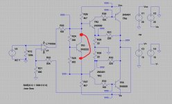
Shorting the bases of Tr2 and Tr3 as indicated is a move I also considered. Tr1 needs investigation in that regard but observing what happened when Tr2 emitter made me think another factor could be an overshadowing black cloud raining on the party below.
The immediate thing to do as you have said is to short the bases of Tr2 and Tr3 and observe the results.
As to measuring the outcomes Martin has one meter and there are no emitter resistors for the output transistors and this makes for a cumbersome process of obtaining various measurements.
The task would be made easier by fitting 5 watt 100R resistors in the power amplifier supply leads. I would fit fuses in the supply lines and wire the resistors in parallel so the tests could be done by removing these from the holders.
I mentioned before the idea of monitoring resistor currents with a moistened finger. One can do that with the supply line resistors and keep the other hand free on the on/off button if the test one heats up. This can be done quickly enough to check both of them in short order.
Last edited:
I am dubious about using a safety bulb here if this of too high a wattage it will provide more protection by reducing secondary current.
The higher the wattage, the less the protection...
There are a lot of possible avenues to explore but at the moment, and with just one channel seemingly affected, concentrating on that channel seems the way forward.
What would help enormously though would be a scope to see what is going on.
@Martin,
In post 19 Ian Finch suggested the light bulb in the transformer primary to you. In the illustration the wattage was 75-100 but in his narrative he recommended 40-60 watts.
In your post 43 you stated that neither channel was working and nearly 1A was being drawn from the positive rail.
Mooly has picked me up on the point that higher bulb wattage types provide less protection which raises the question what value wattage bulb did you use for the tests as in post 43 and was 1A drawn from the positive rail in both channels.
The higher the wattage, the less the protection...
There are a lot of possible avenues to explore but at the moment, and with just one channel seemingly affected, concentrating on that channel seems the way forward.
What would help enormously though would be a scope to see what is going on.
It seems Martin's unit was the 30 watt unit and the alternative 25 volt secondary winding pair allows for use of the same transformer in the 25 watt version.
That being the case the resistor values in the zener supplies ought to be reduced to 70% of their present value if op.amp current output is to remain at the same level as in unmodified state.
In Martin's situation I would seriously consider buying the working example on offer by Paul Kemble's contact. It would perhaps be a cheap way of buying the higher voltage output transformer.
If that unit is the lower output version measuring circuit voltages would help fault diagnosis in Martin's unit and he could take his time in sorting out the problems.
Awaiting the reply, I'd go further and use the smallest bulb to hand that was compatible with the socket, in order to get a clear sign of life. These days, 24W halogen is common for bedlamps etc. and won't be wasted if it's a significant cost.
Still, I can only agree with Mooly that the stark difference between base voltages of Q2 in either channel is the puzzle to solve for the present, even if related to the IC supply voltage and perhaps IC3 itself. 'no harm in posting what the supply voltages at pins 1 and 7 of IC3 are though.
Still, I can only agree with Mooly that the stark difference between base voltages of Q2 in either channel is the puzzle to solve for the present, even if related to the IC supply voltage and perhaps IC3 itself. 'no harm in posting what the supply voltages at pins 1 and 7 of IC3 are though.
Latest progress is that isolating the various components of the power stage makes no difference! (See schematic), alternately lifting a leg of R26 ad R27, then R126 and R127 makes no difference, the remaining channel still seems to take nearly an amp. Anybody got any ideas as to where this energy is going since it is not cooking any of the board components?
https://www.google.co.uk/search?q=te...W-vT4GFasfM:
There is an assumption here that no resistors were cooked when the output transistors failed. R28-R33 could expire those circumstances. I have had that happen without visible signs. I also know of a case using this output stage where a handful of resistors have expired due to a problem relating to an output transistor single or pair.
In post 65 I suggested measuring these resistor values to eliminate failures in any of these as being a possible cause.
Have you done this and come to any conclusions.
Update
Hi all
Not been idle over the past month or so, so thought I'd bring you guys up to speed and hope with a final push we can crack this once and for all.
Just to refresh, now have the unit powered via a current limiter as per discussion, - actually a 60 watt bulb which tends to flash once then go dark.
Have retested the power stage BC 182's and found a dry joint in channel 101. -When resolved, all voltages between channels now the same so assume is good.
Have isolated the zener circuits from the power stage to work out where excess current is going, - makes no difference so cannot be going thru the op amp circuit.
Similarly have split the power going to left and right channels of the power stage, to try and isolate excess current drain, - again, both channels show the same excess so problem must be elsewhere.
Have checked assorted resistors in power stage and all show correct values.
Knotty little bu**er this one, I'm beginning to wonder whether a combination of + and - 25v and using TIP 41C/42Cs may simply present less quiescent resistance to the power supply than previously, and the current is fine as long as its around an amp or less.
Either that or my old meter is up the spout and giving erroneous current readings. I'm surprised none of the assorted problems seem to have caused any further damage to the power stage, - when tested all components look fine.
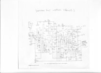
Attached is a reminder of the output stage voltages, - they're now the same on both channels!
Hi all
Not been idle over the past month or so, so thought I'd bring you guys up to speed and hope with a final push we can crack this once and for all.
Just to refresh, now have the unit powered via a current limiter as per discussion, - actually a 60 watt bulb which tends to flash once then go dark.
Have retested the power stage BC 182's and found a dry joint in channel 101. -When resolved, all voltages between channels now the same so assume is good.
Have isolated the zener circuits from the power stage to work out where excess current is going, - makes no difference so cannot be going thru the op amp circuit.
Similarly have split the power going to left and right channels of the power stage, to try and isolate excess current drain, - again, both channels show the same excess so problem must be elsewhere.
Have checked assorted resistors in power stage and all show correct values.
Knotty little bu**er this one, I'm beginning to wonder whether a combination of + and - 25v and using TIP 41C/42Cs may simply present less quiescent resistance to the power supply than previously, and the current is fine as long as its around an amp or less.
Either that or my old meter is up the spout and giving erroneous current readings. I'm surprised none of the assorted problems seem to have caused any further damage to the power stage, - when tested all components look fine.
Attached is a reminder of the output stage voltages, - they're now the same on both channels!
Attachments
Hi all
Have isolated the zener circuits from the power stage to work out where excess current is going, - makes no difference so cannot be going thru the op amp circuit.
Similarly have split the power going to left and right channels of the power stage, to try and isolate excess current drain, - again, both channels show the same excess so problem must be elsewhere.
Have checked assorted resistors in power stage and all show correct values.
Knotty little bu**er this one, I'm beginning to wonder whether a combination of + and - 25v and using TIP 41C/42Cs may simply present less quiescent resistance to the power supply than previously, and the current is fine as long as its around an amp or less.
Attached is a reminder of the output stage voltages, - they're now the same on both channels!
If the resistors have tested OK try some transistor logic.
One way to look at a transistor is a pair of series diodes with a voltage gap at the midpoint needing to be filled by passing a small amount of current through the base to raise increase the potential to 0.6 volts - the voltage at the arrow end of the emitter to base diode junction needs to register the least positive reading of the two connections.
In your circuit TR4 the base and emitter voltages are identical - usually an indication of short circuit failure. On the resistance range of a meter you would get a similarly low reading (in circuit) whichever way the leads are applied.
The fact there is zero volts at the collector of TR4 suggests an open circuit failure within that connection.
You can look at the remaining transistors for the same sorts of possibilities.
Last edited:
- Status
- Not open for further replies.
- Home
- Amplifiers
- Solid State
- Texan Rebuild