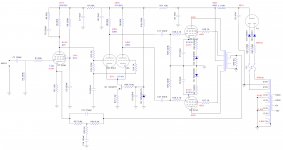
When I rebuilt it, I put everything over to match your simulation schematic. C2 in my schematic has been changed to 220pF. I will give 10K a go.With your 270pF RC is the same as CR
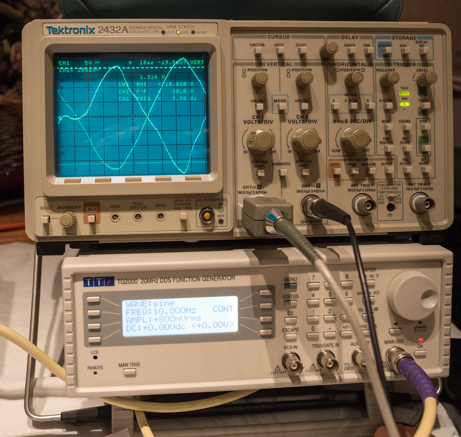
That improved the HF response a tiny bit but the oscillation issue is back exactly as before. This is the plot.
Response plots
The only other changes between now and then are the EF86 and 6CG7 are different. (a mullard NOS EF86 and GE 6CG7 vs a NOS GE 6267 and a modern Electro-harmonix 6CG7) The EF86 cathode resistor is now 1.2K where it was only 1K. I doubt the valves themselves are likely to have much effect.
These are the measured voltages, which do appear to have shifted about quite a bit since the last time I measured them.
I would make R3 1k5 just to bring the voltage on the plate of the ef86 to 90-100v. If you can pick V2 to get the plate voltages similar that would help too. I think if your square waves are fine then ignore the oscillation. I think the output transformer is saturating at this frequency and dropping the loop gain right down - I don't model the saturation so won't see the same effect. You could reduce C1 a bit. I think next time use a an OPT that has better interleaving. Does that scope have an FFT - I would be interested on the THD.
Last edited:
Unfortunately, both of my scopes are nearly 30 years old and cannot do FFT. The only analyser I have is a Lindos LA100 set which is currently not functional.I would make R3 1k5 just to bring the voltage on the plate of the ef86 to 90-100v. If you can pick V2 to get the plate voltages similar that would help too. I think if your square waves are fine then ignore the oscillation. I think the output transformer is saturating at this frequency and dropping the loop gain right down - I don't model the saturation so won't see the same effect. You could reduce C1 a bit. I think next time use a an OPT that has better interleaving. Does that scope have an FFT - I would be interested on the THD.
I'll see if some component tweaking around the cathode of EF86 will help get things back to where they should be.
I started it in January so it's had 9 months of my time so far and it's still only a prototype. With respect to the output transformers, they are very well made but my confidence in using sowter again has been knocked by this. I should have gone single 8 ohm secondary as that is all I ever use.
Anyway, I put R4 back to 22K and changed R7 to 82K which seems to have worked very well for stability. I've tried to upset the apple cart with big LF inputs and not seen anything other than the ugly shapes from saturation.
Ironically, for all the abuse I give the OPT, it does have pretty good LF performance.

I also swapped out the GE 6CG7 for one of the EH parts. The DC balance is now perfect. These are the voltages. Apart from the slightly inferior HF response, this appears to be pretty much perfect. (provided I've reduced the gain sufficiently)
Anyway, I put R4 back to 22K and changed R7 to 82K which seems to have worked very well for stability. I've tried to upset the apple cart with big LF inputs and not seen anything other than the ugly shapes from saturation.
Ironically, for all the abuse I give the OPT, it does have pretty good LF performance.
I also swapped out the GE 6CG7 for one of the EH parts. The DC balance is now perfect. These are the voltages. Apart from the slightly inferior HF response, this appears to be pretty much perfect. (provided I've reduced the gain sufficiently)
Attachments
Kei, you appear to still be playing around with parts and part values, but imho you are still prone to instability issues until such time as you can make a few measurements of gain and phase with no-feedback in order to gauge your gain and phase margins at both ends of the spectrum. Using an OPT of unknown case history in that amp circuit is your Achilles heal, and I suggest doing tests that confirm the basic gain-phase performance as the only reliable way to move forward to an outcome where you can be confident that your various feedback related tweaks are doing what they should be doing.
I have measured it previously just for the transformer, to try and make sense of its performance. I have measured it again today for the whole amp as open loop including lead/lag times and calculated phase shift. I have attached it as a PDF. I have been keeping a spreadsheet with all tests conducted here. There is a workbook for each test at the bottom.
In its current form, I have not been able to trigger any oscillation with the same signals as before which is a good sign. I'm baffled as to why the 10KHz-20KHz region closed loop has similar or slightly less gain than open loop though. (not that it is a significant drop)
In its current form, I have not been able to trigger any oscillation with the same signals as before which is a good sign. I'm baffled as to why the 10KHz-20KHz region closed loop has similar or slightly less gain than open loop though. (not that it is a significant drop)
Attachments
Nice open-loop plot - what do you think your phase error tolerance is on your spot phase measurements?
If you get the chance, I'd recommend doing some repeat open-loop LF testing with lower and higher output signal levels (given the 1W nominal level presently used), as a way of getting a better awareness of how the OPT primary inductance could be influencing LF stability margins. Are you limited to 2Hz min? Just thinking if testing to lower frequency could identify where OPT related roll-off and phase shift occurs, and hence help clarify the accumulating phase shift contributors down at that end.
At the HF end, and below 150kHz, it looks reasonable to apply circa 20dB of feedback based on -20dB response at nearly 80kHz with 45deg phase margin.
Are you able to test above 150kHz? Your open-loop gain is rising again, and may give a higher frequency condition where the amount of feedback needs to be limited/contrained for stability.
Is the first-stage shelf network in circuit for the open-loop test? I don't see any distinct gain droop - maybe the 22k and 82k just provide a shallow gain blip as the OPT roll-off is starting to dominate.
Just to confirm, for the open-loop test, did you disconnect the feedback at the R3 node?
The simulation does not show the gain drop off at HF. Maybe just input capacitance you could drop the input resistor from 22k to 10k on the grid of the ef86 to see if it has any affect.
Based on Roddam (Mar 1951 WW), the first stage gain should step down by about 13dB, with initial -3dB about 9kHz and final shelf being approached at about 40kHz, and with a phase blip that peaks at about 40deg at about 20kHz (from Learned 1944).
The open-loop plot in post #389 shows a -3dB out at about 25kHz, and no phase modification in that region, which doesn't align very well at all. Kei, perhaps worth checking that 220pF is actually 220pF, or something else is NQR.
https://worldradiohistory.com/UK/Wireless-World/50s/Wireless-World-1951-03.pdf
https://dalmura.com.au/static/corrective%20networks.pdf
PS. I just realised you have a 7Hz HPF right at the input - I'd suggest trying to bypass that for open-loop testing.
Last edited:
I'm not 100% certain on the accuracy of these measurements as I'm comparing CH1 to CH2 on the scope using the measure time function between the two traces using the 0 crossing point as the measuring point. Things get confusing once the lag is at or beyond 90 degrees.
All feedback was disconnected when measuring including the step network around the anode of EF86. I realised this morning that I forgot to bypass the input HPF.
I have no LCR meter so cannot check the 220pF capacitor. It is a silver mica part so I'd be less suspicious of it. The 150pF capacitor is polystyrene so it may suffer with the heat.
I know there is a small amount of stray capacitance on the input as a 10KHz square wave shows very slight rounding at the edges after the input filter board. I guess this is down to the foil backed card i used as a screen for the veroboard.
I also checked the current level of feedback which came out to 19.9dB. (45.77dB - 25.87dB) I've not been able to get it to oscillate in it's current form since raising the supply voltage to EF86 slightly. (R7=82k instead of 100k)
Yep I think the 22k input resistor and the short screen cable to the grid may be adding a a bit of HP LPF. There's no reason not to make that 10k there. I think all is correct its just the OPT may be rolling off. I know this is a low first dominate pole but that's what was needed.
I suggest repeating the plot without the input HPF, and shorting out the input 22k would be a good starting point so that the plot provides a clean view of the forward path amp circuit response that is going to be subject to global feedback. Any LF or HF filtering at the input would just muddy the water (so to speak).
Thank you both for the suggestions. Unfortunately, I pulled a muscle in my back yesterday and now cannot move the 2st that the amp weighs in order to do any further testing or make any modifications.
I will look at it again once I can actually move it.
I will look at it again once I can actually move it.
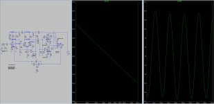
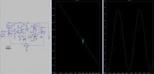
I've not had the room to be able to actually put the amp back under test, hence the lack of updates on this. During this time, I have been looking at the LTspice simulation and having finally figured out how to use it. I have been playing with the feedback components and have to admit to finding the results very bit baffling.
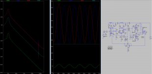
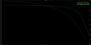
The standard feedback components (C2=220p C13=150p) show some oscillation at around 1.2V input and 10Hz. In the simulation, I've found that lowering C13 and raising C2 seems to cure the instability but what I am finding confusing is the frequency response plot shows a hump in the HF around 30-45Hz. I assume that would show itself as ringing on a square wave? I assumed that the hump in the HF was more likely to cause instability.
The other two images show the difference in the oscillation between using a 6267 vs a 6BR7. I have some of these to try as a cheap EF86 substitute. I think the issue is reduced simply because 6BR7 has a little bit less gain and it would look similar to 6267 if I increased the input signal level slightly.
Attachments

I would caution against trying to extract detailed performance information from your simulation unless you clearly know what part model parameters are causing specific characteristics, and why, and you have confirmed by part model parameter variations and preferably also by actual measurement, that you have a nominal agreement between sim and measurement.
Up until that stage of sim development, you may just be seeing quirky behaviour from a poor model.
Up until that stage of sim development, you may just be seeing quirky behaviour from a poor model.
I would agree that something with the model doesn't seem quite right as the performance for a standard 5-20 is worse than dreadful. I think it's more than likely the output transformer model causing the issues.
In other news, 6BR7 works great as a substitute for EF86 provided the socket is rewired to suit. Benefit is that it's still very cheap to buy, so I may get a dozen or so.
In other news, 6BR7 works great as a substitute for EF86 provided the socket is rewired to suit. Benefit is that it's still very cheap to buy, so I may get a dozen or so.
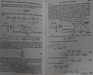
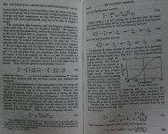
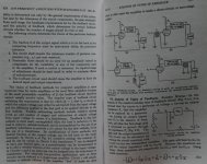
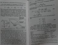
As I am into this vary same challenge, I red this wartime text and applied the "phase advance" and "phase-retard" RC network depicted in figure 9.4a. In the region of the characteristic the phase is relatively constant with respect to frequency. Maybe of help.
Attachments
- Home
- Amplifiers
- Tubes / Valves
- Testing newly built mullard 5-20