Is a Variac the only way to load the PSU without using the tubes? Or can I infer a resistor value from the schematic?
Anything else I am missing?
The initial test is to test grounds and chassis ground (ie from tube sockets to earth pin with the system disconnected from mains.
Next is simply go through the amp (disconnected from mains) to test the live/return portions vs chassis ground with a continuity tester/ohmmeter.
Once you know there's a ground path and no simple shorts.. start testing with no tubes in first. Then I would use a pair of cheap but functional tube(s) for initial testing and listening tests then once it's been happy for a while (ie at least a week of operating then worry about the vintage stuff).
Last edited:
A properly fused Variac would be best.
And current limiting - a DIY alternative to an all singing power supply is the humble filament lightbulb.
Yes. You'll expect about 300 VDC at roughly 40mA, so a resistor across the B+ of 300/.040 = 7500 Ohms is plenty close enough. Actually, anything between 5K and 10K Ohms is closer than you need. Long term, it will dissipate 300 x .040 = 12 Watts, so needs to be big enough to survive this, and to either be suspended (safely!) or to sit on some baking tins or something.
This process is inherently dangerous, so needs to happen in a room with no access by children or pets. Nuf said.
Ohm's Law thinking will become as integral to you as your ABCs as time goes by. But safety needs constant refreshment, so please forgive me if I'm too strident.
All good fortune,
Chris
This process is inherently dangerous, so needs to happen in a room with no access by children or pets. Nuf said.
Ohm's Law thinking will become as integral to you as your ABCs as time goes by. But safety needs constant refreshment, so please forgive me if I'm too strident.
All good fortune,
Chris
Note that variacs and series lamps will not automatically protect against soaring voltages from unloaded choke input supplies. A variac, used with vigilance, and not allowing B+ to exceed capacitor ratings, will however let you test your wiring, etc., so is still useful if used thoughtfully.
All good fortune,
Chris
All good fortune,
Chris
Note that variacs and series lamps will not automatically protect against soaring voltages from unloaded choke input supplies. A variac, used with vigilance, and not allowing B+ to exceed capacitor ratings, will however let you test your wiring, etc., so is still useful if used thoughtfully.
Good catch about the unloaded chokes and also output transformer.
Also - check the rating of the wiring as you go through and check. I see you have an elevated heater so check the elevation + heater AC doesn't go above the insulation rating.
Not much to add, a varaic and scope helps but you may be able to get away without. After checking connections and connecting a dummy load, a 8r or whatever on a heatsink or an old speaker, just power it up with the valves in through a lamp limiter, hand on off switch. Valves are pretty robust, not like trannies,you are winging it though.
In place of a variac wire 3 lightbulbs in series and either switch them out or jumper them out,that'll reduce HT/B+.
Clip a voltmeter on the 45 cathode to make sure it's biased ok then take some voltage readings looking out for smoke and smells. It'd be an idea to knock up a capacitor discharger to get rid of charge in caps.
Andy.
Last edited:
That's a fair point, and I find myself usually way too conservative about homebrew stuff. If it were somebody else's, you have a responsibility to protect it as well as can be done, but if it's yours, you can take a flyer if needed. *Except safety!* *No exceptions there.*
Thanks Andy for the excellent and practical ideas.
Chris
Thanks Andy for the excellent and practical ideas.
Chris
Hm... forgive me for stating the obvious, but I sense a misunderstanding...
A Variac goes between your amplifier (the "Device under test") and the wall. It lets you slowly bring the input voltage up so that your untested circuit doesn't immediately see the full B+ voltage. Its purpose is to allow you to catch any wiring faults using your "slow" senses (sight, smell, hearing) that otherwise would happen too fast for you to catch.
A dim bulb tester also goes between your amplifier and the wall. Its purpose is to limit the amount of current that is permitted to flow. If you have a short, for example, the bulb will "soak" up the excess current (converting it to light and heat) and also give you a visual indication that something is wrong (glows very brightly; in normal operation it should probably be only slightly lit).
If you are unsure of the state of the circuit, both of these tools help you troubleshoot before it becomes also a repair job.
However if I could simulate the load with a lightbulb as somebody suggested, I will try that.
Is a Variac the only way to load the PSU without using the tubes?
A Variac goes between your amplifier (the "Device under test") and the wall. It lets you slowly bring the input voltage up so that your untested circuit doesn't immediately see the full B+ voltage. Its purpose is to allow you to catch any wiring faults using your "slow" senses (sight, smell, hearing) that otherwise would happen too fast for you to catch.
A dim bulb tester also goes between your amplifier and the wall. Its purpose is to limit the amount of current that is permitted to flow. If you have a short, for example, the bulb will "soak" up the excess current (converting it to light and heat) and also give you a visual indication that something is wrong (glows very brightly; in normal operation it should probably be only slightly lit).
If you are unsure of the state of the circuit, both of these tools help you troubleshoot before it becomes also a repair job.
With the simple circuit that is the OP's amp, barring any really stupid mistakes like connecting a cap the wrong way round, you should be ok with a just lamp limiter. I'd recommend an old speaker as the dummy load instead of a resistor you'll hear if something is wrong.
I go over all my work with a magnifying glass, and give each solder joint a tug with pliers, especially grid and cathode resistors. Even so, accidents happen and I often have brain farts, I've done some really daft things, but valves are very forgiving. I powered my latest amp build up the other day and sensed more than average heat, a double triode, a 2C34 was happily glowing bright orange, the fixed bias voltage had failed. Replaced the negative supply fuse, no harm done.
Talking of fuses and fusing, make sure your HT/B+ is fused, on the AC before your rectifier, pop a lower than spec fuse in, a fast blow 100mA say, if there is any gross short it'll blow.
Trying to think of practical tips.... on fixed bias amps I always pop my meter onto the OP valve grids, no bias voltage - SW off quick. In your case pop your meter's red lead onto the grid, black lead onto the cathode, if you don't see a negative voltage, SW off.
You could also put a big 1k resistor after the chokes and reservoir caps on your HT/B+ to limit current on first power up, pop your meter across it to monitor current.
Lastly, power your amp up for the first time when your fresh and wide awake, in the morning rather than after a day working on the amp, that way you should catch any screw ups quickly.
An isolation transformer, variac, scope and other kit is nice, but you can do without, just have a think before powering up, go steady, make sure your safe and go for it. Good luck, Andy.
Last edited:
Hm... forgive me for stating the obvious, but I sense a misunderstanding...
A Variac goes between your amplifier (the "Device under test") and the wall. It lets you slowly bring the input voltage up so that your untested circuit doesn't immediately see the full B+ voltage. Its purpose is to allow you to catch any wiring faults using your "slow" senses (sight, smell, hearing) that otherwise would happen too fast for you to catch.
A dim bulb tester also goes between your amplifier and the wall. Its purpose is to limit the amount of current that is permitted to flow. If you have a short, for example, the bulb will "soak" up the excess current (converting it to light and heat) and also give you a visual indication that something is wrong (glows very brightly; in normal operation it should probably be only slightly lit).
Thanks for the clarification. Indeed my initial understanding was that the bulb would provide the load. I underrstood better after reading the article suggested:
This is guitar amp related, but should be similar: Amp Startup
That's a great simple tutorial on how to bulid and use a current limiter. Thanks!
Good luck, Andy.
Wow so many great tips! This whole subject thread is full of such simple but great tips, I'm tempted to make a big list. I've just been going with a variac and 4 or 5 multimeters to watch all at once. I stick a post it note with the normal expected voltage range on each then just watch them as I turn up the juice. But thats not the best way if there is a failure mode somewhere. Something as simple as making a bench outlet where I could pop in a well underrated fuse is a no brainer.
Or if I'm going to make myself a dim bulb outlet some day, maybe also add a rotary swatch where I can select from an array of fuse currents, and switching to bypass the bulb, or switch in different wattages, add a red panic emergency stop button, etc. Protection should start at the mains.
https://www.amazon.com/APIELE-Mushr...1629562677&sprefix=stop+button,aps,298&sr=8-4
Last edited:
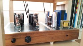
I finally got to finish this project and I have to say it's been a great learning experience. Mostly I have to thank Gordon Rankin for walking me through my errors.
Grounding required some reading and thinking, but surprisingly, after doing my due diligence, I found the amp to be very quiet. My grounding setup is summarized here: https://www.diyaudio.com/forums/construction-tips/370867-grounding-suggestion.html#post6846339
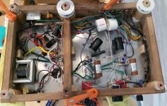
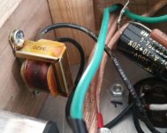
A wiring mistake with the filament transformer caused too much current draw on the chokes (3x their rating) which "baked" them (they are still functioning but the smaller ones have the paper wrapping turned brown). I figured they are damaged by now so I ordered new ones, the larger ones with a higher rating.
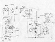
See updated schematics with some corrections and new ratings.
I think it's early to judge the sound with damaged chokes and barely 12 hours of burn-in for NOS tubes, but it sounds very, very promising. Better than my 300B already.
I'm using a pair of National Union 45 and General Electric JAN 12AY7. Edcor power tx (with a separate filament tx for the 45s), One Electron UBT-2 (early US-made vesion) OPT and Hammond chokes; CE Manufacturing caps for the Pi filter, Miflex and Mundorf in the signal path.
My 96dB/W Audio Nirvana Classic 10" are dragging their feet a little bit, I have to crank the volume up to 3/4 and up to get good volume, but they are OK for now. Later I might look at some Lowther DX3, DX4 or other 98+dB full rangers. Would 8 Ohm or 16 Ohm speakers be better for this amp?
Thanks to everybody in this forum for the help, it's been a great fun with rewarding results. In the spirit of this community, I can offer any advice even though I am among the least knowledgeable of the bunch.
gm
Grounding required some reading and thinking, but surprisingly, after doing my due diligence, I found the amp to be very quiet. My grounding setup is summarized here: https://www.diyaudio.com/forums/construction-tips/370867-grounding-suggestion.html#post6846339
A wiring mistake with the filament transformer caused too much current draw on the chokes (3x their rating) which "baked" them (they are still functioning but the smaller ones have the paper wrapping turned brown). I figured they are damaged by now so I ordered new ones, the larger ones with a higher rating.
See updated schematics with some corrections and new ratings.
I think it's early to judge the sound with damaged chokes and barely 12 hours of burn-in for NOS tubes, but it sounds very, very promising. Better than my 300B already.
I'm using a pair of National Union 45 and General Electric JAN 12AY7. Edcor power tx (with a separate filament tx for the 45s), One Electron UBT-2 (early US-made vesion) OPT and Hammond chokes; CE Manufacturing caps for the Pi filter, Miflex and Mundorf in the signal path.
My 96dB/W Audio Nirvana Classic 10" are dragging their feet a little bit, I have to crank the volume up to 3/4 and up to get good volume, but they are OK for now. Later I might look at some Lowther DX3, DX4 or other 98+dB full rangers. Would 8 Ohm or 16 Ohm speakers be better for this amp?
Thanks to everybody in this forum for the help, it's been a great fun with rewarding results. In the spirit of this community, I can offer any advice even though I am among the least knowledgeable of the bunch.
gm
Attachments
Also, I forgot to mention that I built a simple lightbulb current limiter as referred in this thread. I started with a 200W bulb and went down to a 40W one. The bulb got almost full bright on power on and went down to a faint glow after 1-2 seconds (I guess the caps filled up).
The current limiter did not seem to detect the excess current draw on the chokes, unfortunately, but was good to hook it up for other safety reasons.
The current limiter did not seem to detect the excess current draw on the chokes, unfortunately, but was good to hook it up for other safety reasons.
I finally got to finish this project and I have to say it's been a great learning experience. /QUOTE]
It looks great and yeah that one transformer looks a bit toasted.
Well done, every build teaches us something new. Looking at your build pictures and looking at your ground bus, it's a good idea to ground each stage to one point on the bus rather than spaced out, especially the IP and first stage components, oh and make high current draw grounds like the OP stage the nearest to power supply main ground point.
Andy.
Andy.
- Home
- Amplifiers
- Tubes / Valves
- Testing a new build