Hi there,
I am close to completing the assembly and wiring of my first point to point SET amp design and I'm almost ready to test the live circuitry. I have a sort of plan to minimize catastrophic failures, but I could also use some advice and tips from experts.
The design is a 6072A + 45 SET with a 5AR4 rectifier (the classic Bugle).
My plan so far:
1. Double check wiring.
2. Triple check wiring.
3. Apply dummy load to output (for a 45, I assume a 5W resistor per channel should be enough?).
4. Turn on system without tubes. Test voltage to rectifier, heaters, and other critical points.
5. Plug in rectifier (obviously after powering off), test B+.
6. Plug in first stage, test voltages to stage 2.
7. Plug in stage 2, test voltage to output.
8. Plug in line source, replace dummy load with sacrificial loudspeakers, set volume to zero, play music, slowly raise volume
9. Wipe forehead sweat and proceed with sound tests.
I only have a couple of nice vintage 45's, would it be worth looking up some cheap ones (worn out, etc.) on eBay just for a first run? Or should I be OK if the voltages are looking right?
Anything else I am missing?
Thanks.
If you're talking about some known good and tested globe shaped 45 tubes, then get some more used, less expensive 45 tubes.
Otherwise, if your voltages check out good, plug in whatever 45 tubes you have and enjoy.
Other than loudness, I still haven't figured out if I like the sound of the 45 or 300B output tubes? The 300B is louder, and the 45 tubes sound very nice all around. Tough choice for me.
Otherwise, if your voltages check out good, plug in whatever 45 tubes you have and enjoy.
Other than loudness, I still haven't figured out if I like the sound of the 45 or 300B output tubes? The 300B is louder, and the 45 tubes sound very nice all around. Tough choice for me.
Do you suggest a dummy load on the rectifier?
A properly fused Variac would be best.
All Diy tube amplifiers need a B+ bleeder.
Diy means that a knowledgeable person, or an un-knowledgeable person may get inside.
Commercial Tube Amplifiers have a disclaimer on the outside of the bottom cover.
Something like this:
No user serviceable parts inside. Refer all repairs to a professional service person.
And, we still have not seen a schematic with parts values.
Such as 325V-0-325V secondary, and 400V electrolytic caps, 400V coupling caps (those might not work for long, even with a delayed warm-up rectifier; it depends on the exact circuit, varying tube warm-up times, and how conservative the parts maximum voltages are specified).
Do you suggest a dummy load on the rectifier?
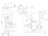
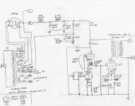
The schematics are a bit messy because I modified the original design on the author's advice. I will scan them later today and post them here. Thanks.
It will be interesting to see the modifications to the Bugle 45.
https://www.wavelengthaudio.com/bugle.pdf
This may sound a bit 'over the top', but I really do recommend investing in a piece of old, old school test equipment. An oscilloscope. One doesn't even need a particularly new one. Indeed … anything from the 1990s is almost sure to be good enough, and would likely come with the ever important high voltage leads.
Thing is, with this piece of kit, you can SEE the waveforms that the amplifier is amplifying. You can see the various voltage levels through the power supply. See ripple. See asymmetries. Ask questions here about them.
Lastly, I also highly recommend building a little 25 watt dummy load by purchasing a bunch of 1 Ω, 2 watt resistors and hooking them simple series to get 8 Ω, and in more clever series-parallel configurations to get other ohmages and power dummy load levels. Remember: to your circuit, the wattage of the dummy load is immaterial. It is the ohmage, the resistance, and the resistance alone that your circuit will 'feel'.
Anyway.
Remembering my youth, and the crazy 'lights turned on' moment…
When I powered up my first oscilloscope, and looked at the waveforms.
The hours, and hours I had spent trying to get 'it' to sound better were instantaneously revealed: I had big power supply problems, along with radio-frequency oscillation. Curing those two (guided by the scope) lead to a revolution in what that amp could do.
Naturally.
⋅-⋅-⋅ Just saying, ⋅-⋅-⋅
⋅-=≡ GoatGuy ✓ ≡=-⋅
It will be interesting to see the modifications to the Bugle 45.
https://www.wavelengthaudio.com/bugle.pdf
Thanks for including the original design.
I got in touch with Gordon Rankin who suggested the modifications in the attached version (I just redrew it from scratch because my annotations on his design got out of control. I also had a hard time finding the recommended transformers so I got similar ones).
Attachments
the Force is strong in this thread.
All good fortune,
Chris
Yes, the Force... Being a hobbyist with very little budget (and apt. space) for a Variac and an oscilloscope which I wil probably use only for this project, I'm kind of sticking to the script. However if I could simulate the load with a lightbulb as somebody suggested, I will try that.
Note that my schematics above has no voltage readings except for the B+ and power sources. I should be able to infer them but it would be nice to have some checkpoints. I might nag Mr. Rankin again (or whoever has built this amp successfully) for that.
- Home
- Amplifiers
- Tubes / Valves
- Testing a new build