Most distortion analyzers are limited to 100V RMS. The HP 333/334 go to 300V as does the Boonton 1120/1121. However if you are testing KW amps you need big load resistors (and 20A+ power). The load resistor can be configured with suitable taps to work with a QA403, probably a safer solution as well. You need to know and configure for unbalanced and balanced outputs in this case so the common mode is within the range of the QA403.
I don't like to daisychain different devices, but devices with all tools inside I need. Shure it would be possible to create an attentuator, but you have to check and calibrate the whole chain again, AC and DC, balanced and unbalanced.
I like more a single device with attentuator, balanced input and driver and so on in one housing, well calibrated and simple. But it has to fit my recommendations, that means a range 1V - 100V RMS input voltage 10 - 20.000 Hz.
I like more a single device with attentuator, balanced input and driver and so on in one housing, well calibrated and simple. But it has to fit my recommendations, that means a range 1V - 100V RMS input voltage 10 - 20.000 Hz.
I own the HP 339A, a good device up to 300V, but without FFT and frequency response. And the floating input only some 30V, not enough for bridged amps.
Have been doing that for years when I was working with PA stuff, takes literally a couple of minutes at most.Shure it would be possible to create an attentuator, but you have to check and calibrate the whole chain again, AC and DC, balanced and unbalanced.
Or you just simply design a simple circuit, calibrate it once, check it once in a while. meh
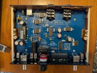
Just finished assembling Pete Millet's sound card interface with the new boards. I had to change R15 from 15k to 39k to get the Full Scale adjustment to read on the display correct.

Hi, I wanted to use a pm device in front of my USD Volt 2 but I didn‘t got one.
Now I bought a Quantqasylum QA403 and I‘m very happy.
With a simple 3-resistor 3-way attenuator 0dB, -20dB and -40dB (switchable from symm to asymm) I get a noisefloor around -130dB and a max inputvoltage of 120V RMS.


Front of load resistor before installing the attenuator

8 ohm 500W, 4 ohm and 2 ohm 1000W
Now I bought a Quantqasylum QA403 and I‘m very happy.
With a simple 3-resistor 3-way attenuator 0dB, -20dB and -40dB (switchable from symm to asymm) I get a noisefloor around -130dB and a max inputvoltage of 120V RMS.
Front of load resistor before installing the attenuator
8 ohm 500W, 4 ohm and 2 ohm 1000W
Are you not using the QA403 attenuator?With a simple 3-resistor 3-way attenuator 0dB, -20dB and -40dB (switchable from symm to asymm) I get a noisefloor around -130dB and a max inputvoltage of 120V RMS.
Jan
Quantasylum doesn't release the QA403 for high power measurements and the max input voltage is restricted to 40V RMS.
They commend to install an attentuator in front of the QA403 to bring the input signal in the range of 1 - 3 V RMS to protect the built in attentuator from higher voltages.
Today I measured a RedRock Modus 4.5 poweramp (1HE stereo), which delivers per channel 500 - 600W from 2 to 8 ohms (in bridged mode up to 1000W at 4 ohms). That means voltages at the load up to 80 V RMS. My -40dB attenuator brings this down to 8 V RMS, which can be safely handled by the QA403. If you damage the built in attenuator, it will be an expensive repair. I have only to tell the software, that there is an attenuation in front and it's all ok.
BTW: If I feed the amp with an asymmetrical signal (like 6,3 mm mono plugs) -40dB means -40dB. If I feed the amp with a symmetrical signal (XLR), I have to give in -34dB attenuation (-6dB less because of the symmetrical signal).
The only part missing from your room heater is the fan. I see you used substantial switches. Important since 1 KW into 2 Ohms is 22A RMS which exceeds most typical switches.
I don‘t use the resistor für longer times, the QA403 is switching the signal on and off for the measurement, so it doesn‘t reach higher temperatures. But shure I thought in installing two 80mm fans.
Both contacts of the switches (specified 25A at 125V) are in parallel and I don‘t use them under load.
Both contacts of the switches (specified 25A at 125V) are in parallel and I don‘t use them under load.
That is one of the nice things of the QA403. It does many measurements with signal bursts which allow full power testing without overheating and without causing power supply sag.
I submitted my QA403 review to aX recently and it will probably be published later this year.
Bob Cordell has created a lot of testing scripts for the '403 that will be available free of charge from his website by the time the review is published. Watch this space!
Jan
I submitted my QA403 review to aX recently and it will probably be published later this year.
Bob Cordell has created a lot of testing scripts for the '403 that will be available free of charge from his website by the time the review is published. Watch this space!
Jan
I bought a complete build first generation analyzer when @spaceistheplace got sick and sold his stuff. Problem is, it seems is not working, the LCD screen is blank. Does anybody has the build/troubleshoot instructions for the first generation PCB? I would really appreciate to get this device working. Keep in mind I am a NOOB. I recently started this hobby and I have so much to learn. So far I checked the DC input and seems to work, the fuse is also intact. I dont know what I should check from here on.
Attachments
There seems to be copper tape beneath the board. Check that it is not making any contact with the board.I dont know what I should check from here on.
I took the board out of the enclosure. I am not sure where the LCD screen should be inserted, there is the 2 rows female connector but the LCD has just one row. The screen was inserted in the bottom row which it could be wrong. I looked on the back of the PCB and it looks the top row has traces connected to it, the bottom row as far as I can tell there are no traces. Should I insert the LCD on the top row?
First I looked at Pete Millet website and I could not find a build/troubleshoot manual, I found just the description of the device and the schematics. On this thread I am at page 26, so far I didnt find any information that I can use at this stage.
First I looked at Pete Millet website and I could not find a build/troubleshoot manual, I found just the description of the device and the schematics. On this thread I am at page 26, so far I didnt find any information that I can use at this stage.
Attachments

First steps. Check the output voltages on the NDT module. Check voltages after the on/off switch. Check the input and output on the 5volt regulator.I bought a complete build first generation analyzer when @spaceistheplace got sick and sold his stuff. Problem is, it seems is not working, the LCD screen is blank. Does anybody has the build/troubleshoot instructions for the first generation PCB? I would really appreciate to get this device working. Keep in mind I am a NOOB. I recently started this hobby and I have so much to learn. So far I checked the DC input and seems to work, the fuse is also intact. I dont know what I should check from here on.
yes, I just tried, the LCD goes on the top row. Now I need to know how to adjust/test the board since I see there are a couple of adjustable pots on it.
Those 2 adjustments are explained in Pete Millett's website. Not critical for operation.
- Home
- Design & Build
- Equipment & Tools
- Test & Measurement interface for Soundcard