You're welcome!
FWIW: http://www.diyaudio.com/forums/full...e-fostex-craft-handbooks-110.html#post4903502
GM
If I understand your post correctly you're saying that 4 inches from the floor is a starting point, or that increasing the length of the front and sides by 4 inches or less is a potential solution.
Sorry, I'm very new to speaker building. Currently reading through the quarter wave site.
Also, I've read something about using Fs*.707 as a turning frequency. I've also read the FS of my drivers gets lower as it is broken in.
Does this mean I should use an Fs lower than the measured 85hz?
I plan using passive EQ, but without series resistance fortunately.
Hmm, what passive EQ can you use that doesn't include some series resistance?
GM
Again forgive my ignorance, is the tendency on me to idealize things, just forgot the resistance of cables, as superconductors are out of my budget, I must add at least about 15mΩ/m.
I think that I got it, nonetheless it can be wrong, I am getting old too fast, almost relativistically 😀
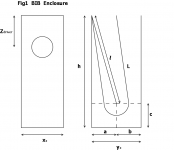
Let's consider a BIB enclosure like that on the figure

Using simple euclidean geometry, the length of the horn is given by
L = √(4 h² - 8 a h + 5 a²) + (π a/2)
The height of the enclosure is given by the solution of
4 h² - 8 a h + 5 a² - [L - (π a/2)]² = 0
With
L = c' / (2 Fs)
c' = 340 m/s (speed of sound)
The volume of the enclosure is given by
Vb = 20 Vas Qts^(5/4)
The internal septum has a volume which is not negligible, in the order of some liters, and it is given by
Vint = l xo d = √(h² - 2 a h + 2 a²) xo d
d = septum thickness
Then, the total volume of the enclosure is given by
V = Vb + Vint
Then, the terminus area should be
Sm = V / h
The other imposed condition is
yo = √2 xo
Then
Sm = xo yo = √2 xo² = (√2/2) yo²
Then, the width of the enclosure will be
xo = √[(√2/2) Sm]
The depth of the enclosure will be
yo = √(√2 Sm)
Zdriver will be given by
Zdriver = 0.217 L
Finally
a = b = c = yo/2
Note that we need an iterative method (e.g. Newton) starting with the approximation
h ∼ L/2
Let's consider a BIB enclosure like that on the figure
Using simple euclidean geometry, the length of the horn is given by
L = √(4 h² - 8 a h + 5 a²) + (π a/2)
The height of the enclosure is given by the solution of
4 h² - 8 a h + 5 a² - [L - (π a/2)]² = 0
With
L = c' / (2 Fs)
c' = 340 m/s (speed of sound)
The volume of the enclosure is given by
Vb = 20 Vas Qts^(5/4)
The internal septum has a volume which is not negligible, in the order of some liters, and it is given by
Vint = l xo d = √(h² - 2 a h + 2 a²) xo d
d = septum thickness
Then, the total volume of the enclosure is given by
V = Vb + Vint
Then, the terminus area should be
Sm = V / h
The other imposed condition is
yo = √2 xo
Then
Sm = xo yo = √2 xo² = (√2/2) yo²
Then, the width of the enclosure will be
xo = √[(√2/2) Sm]
The depth of the enclosure will be
yo = √(√2 Sm)
Zdriver will be given by
Zdriver = 0.217 L
Finally
a = b = c = yo/2
Note that we need an iterative method (e.g. Newton) starting with the approximation
h ∼ L/2
Attachments
Last edited:
You make it seems very easy, a detailed calculation is all that one wants, thanks again.
Indeed I will use a high output impedance (in the order of 1Ω) valve amplifier.
You're welcome!
My part was easy or I couldn't have done it; read Thiele's and Small's JAES papers to see all the math they had to figure out to make it simple for me [scroll down]: Read Research - Articles
OK, so with the BIB calculator's built in allowance for a certain amount of driver specs variance, typical passive XO, speaker wiring losses and with only 1 ohm added for the amp, then no need to make the cabs larger unless you just want to for a little extra acoustic efficiency. Had you an F1 amp though with its 80 ohms it would increase the cabs to a pair of large closets.
GM
Define 'old'.......looked up where you live; that's a seriously beautiful area! Beats any place I can easily drive or fly to.
I'll take your word for the math..........
GM
I'll take your word for the math..........
GM
My part was easy or I couldn't have done it; read Thiele's and Small's JAES papers to see all the math they had to figure out to make it simple for me [scroll down]: Read Research - Articles
That's a lot to read! Thanks again!
OK, so with the BIB calculator's built in allowance for a certain amount of driver specs variance, typical passive XO, speaker wiring losses and with only 1 ohm added for the amp, then no need to make the cabs larger unless you just want to for a little extra acoustic efficiency. Had you an F1 amp though with its 80 ohms it would increase the cabs to a pair of large closets.
GM
OK, great advice, all for the sound.
Define 'old'.......looked up where you live; that's a seriously beautiful area! Beats any place I can easily drive or fly to.
One is getting old when a simple calculation takes ages...
Yes, I live in a beautiful place, if someday you want to visit me just tell me, seriously! I live modestly with my wife and the house is old but big, at least for our standards.
I'll take your word for the math..........
GM
Those math are just the beginning, I must to re-read about Newton iteration method, or just make a lot of calculations with my old Casio...
If you find any error please tell me.
Just to check the equations of post#5623, maybe it will be useful for someone...
T/S parameters
Qts = 0.201, Vas = 60.1 l = 60100 cm³, Fs = 42 Hz
Invariants
L = c' / (2 Fs) = 404.762 cm
Zdriver = 0.217 L = 87.83 cm
Vb = 20 Vas Qts^(5/4) = 161.77 l = 161770 cm³
Initial values
ho = L/2 = 202.381 cm
Vinto = 0
Vo = Vb = 161770 cm³
Smo = Vo / ho = 799.33 cm²
xoo = √[(√2/2) Smo] = 23.77 cm
yoo = √(√2 Smo) = 33.62 cm
ao = yoo/2 = 16.81 cm
d = 1.80 cm
First Iteration
Vint1 = √(ho² - 2 ao ho + 2 ao²) xoo d = 7972.35 cm³
V1 = Vb + Vint1 = 169742.35 cm³
Sm1 = V1 / ho = 838.73 cm²
xo1 = √[(√2/2) Sm1] = 24.35 cm
yo1 = √(√2 Sm1) = 34.44 cm
a1 = b1 = c1 = yo1/2 = 17.22 cm
4 h1² - 8 a1 h1 + 5 a1² - [L - (π a1/2)]² = 4 h1² - 137.76 h1 - 141184.38 = 0
h1 = 205.88 cm
Second Iteration
Vint2 = √(h1² - 2 a1 h1 + 2 a1²) xo1 d = 8303.34 cm³
V2 = Vb + Vint2 = 170073.34 cm³
Sm2 = V2 / h1 = 826.08 cm²
xo2 = √[(√2/2) Sm2] = 24.17 cm
yo2 = √(√2 Sm2) = 34.18 cm
a2 = b2 = c2 = yo2/2 = 17.09 cm
4 h2² - 8 a2 h2 + 5 a2² - [L - (π a2/2)]² = 4 h2² - 136.72 h2 - 141361 = 0
h2 = 205.85 cm
Third Iteration
Vint3 = √(h2² - 2 a2 h2 + 2 a2²) xo2 d = 8245.78 cm³
V3 = Vb + Vint3 = 170015.78 cm³
Sm3 = V3 / h2 = 825.92 cm²
xo3 = √[(√2/2) Sm3] = 24.17 cm = xo2 ==> Convergence
yo3 = √(√2 Sm3) = 34.18 cm = yo2 ==> Convergence
a3 = b3 = c3 = yo3/2 = 17.09 cm = a2 = b2 = c2 ==> Convergence
4 h3² - 8 a3 h3 + 5 a3² - [L - (π a3/2)]² = 4 h3² - 136.72 h3 - 141361 = 0
h3 = 205.85 cm = h2 ==> Convergence
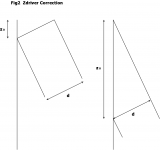
Some corrections

The correction for L, ∆L is negligible because correction in the upper corner almost cancels with correction on the bottom.
For the correction in Zdriver we must distinguish two cases
i) Poor skills in woodwork (my case), left side on Fig2
zo = d sin(θ)
ii) Amazing skills in woodwork, right side on Fig2
zo = d / sin(θ)
θ = tan⁻¹[a / (h - a)]
Seems to me that the cut is almost impossible... so, forget this case.
Final Results
L = 404.762 cm
h = 205.85 cm
V = 170015.78 cm³
Sm = 825.92 cm²
xo = 24.17 cm
yo = 34.18 cm
a = b = c = 17.09 cm
Zdriver = 87.99 cm
T/S parameters
Qts = 0.201, Vas = 60.1 l = 60100 cm³, Fs = 42 Hz
Invariants
L = c' / (2 Fs) = 404.762 cm
Zdriver = 0.217 L = 87.83 cm
Vb = 20 Vas Qts^(5/4) = 161.77 l = 161770 cm³
Initial values
ho = L/2 = 202.381 cm
Vinto = 0
Vo = Vb = 161770 cm³
Smo = Vo / ho = 799.33 cm²
xoo = √[(√2/2) Smo] = 23.77 cm
yoo = √(√2 Smo) = 33.62 cm
ao = yoo/2 = 16.81 cm
d = 1.80 cm
First Iteration
Vint1 = √(ho² - 2 ao ho + 2 ao²) xoo d = 7972.35 cm³
V1 = Vb + Vint1 = 169742.35 cm³
Sm1 = V1 / ho = 838.73 cm²
xo1 = √[(√2/2) Sm1] = 24.35 cm
yo1 = √(√2 Sm1) = 34.44 cm
a1 = b1 = c1 = yo1/2 = 17.22 cm
4 h1² - 8 a1 h1 + 5 a1² - [L - (π a1/2)]² = 4 h1² - 137.76 h1 - 141184.38 = 0
h1 = 205.88 cm
Second Iteration
Vint2 = √(h1² - 2 a1 h1 + 2 a1²) xo1 d = 8303.34 cm³
V2 = Vb + Vint2 = 170073.34 cm³
Sm2 = V2 / h1 = 826.08 cm²
xo2 = √[(√2/2) Sm2] = 24.17 cm
yo2 = √(√2 Sm2) = 34.18 cm
a2 = b2 = c2 = yo2/2 = 17.09 cm
4 h2² - 8 a2 h2 + 5 a2² - [L - (π a2/2)]² = 4 h2² - 136.72 h2 - 141361 = 0
h2 = 205.85 cm
Third Iteration
Vint3 = √(h2² - 2 a2 h2 + 2 a2²) xo2 d = 8245.78 cm³
V3 = Vb + Vint3 = 170015.78 cm³
Sm3 = V3 / h2 = 825.92 cm²
xo3 = √[(√2/2) Sm3] = 24.17 cm = xo2 ==> Convergence
yo3 = √(√2 Sm3) = 34.18 cm = yo2 ==> Convergence
a3 = b3 = c3 = yo3/2 = 17.09 cm = a2 = b2 = c2 ==> Convergence
4 h3² - 8 a3 h3 + 5 a3² - [L - (π a3/2)]² = 4 h3² - 136.72 h3 - 141361 = 0
h3 = 205.85 cm = h2 ==> Convergence
Some corrections
The correction for L, ∆L is negligible because correction in the upper corner almost cancels with correction on the bottom.
For the correction in Zdriver we must distinguish two cases
i) Poor skills in woodwork (my case), left side on Fig2
zo = d sin(θ)
ii) Amazing skills in woodwork, right side on Fig2
zo = d / sin(θ)
θ = tan⁻¹[a / (h - a)]
Seems to me that the cut is almost impossible... so, forget this case.
Final Results
L = 404.762 cm
h = 205.85 cm
V = 170015.78 cm³
Sm = 825.92 cm²
xo = 24.17 cm
yo = 34.18 cm
a = b = c = 17.09 cm
Zdriver = 87.99 cm
Attachments
Last edited:
Showoff! 😉 No clue what the 'corrections' are about, but are strictly academic until we can hear an audible phase shift in its response. Still, it's nice to finally have a proper design routine rather than just my 'back of napkin' doodling that doesn't engender much confidence in its performance potential.
Thanks! 😀
GM
Thanks! 😀
GM
Showoff! 😉 No clue what the 'corrections' are about, but are strictly academic until we can hear an audible phase shift in its response. Still, it's nice to finally have a proper design routine rather than just my 'back of napkin' doodling that doesn't engender much confidence in its performance potential.
Thanks! 😀
GM
I just did follow your procedure with a correction that take into account for the volume of internal septum, in this case more than 8 liters!...
As I said before, I just have an old scope and a couple of multimeters, so a precise calculation is paramount for me, I have only one chance, a silver bullet...
Calculations are not to showoff in any way, I still wait for some criticism, I also said before that my ignorance in this matter is superlative, I am a simple apprentice following his master and making mistakes all the time, hope that moderators could change a couple of sub-indices...
BTW, the correct expressions are
V2 = Vb + Vint2 = 170073.34 cm³
V3 = Vb + Vint3 = 170015.78 cm³
I still hope that moderators can correct them.
The last question: With Zdriver=0.217 L the speaker's magnet will touch the septum, what do you suggest?
Last edited:
The last question: With Zdriver=0.217 L the speaker's magnet will touch the septum, what do you suggest?
This one is easy. Carve out enough space for the magnet. If you can't do that without going through the separator then you can add a piece of wood in front of the front panel to support the speaker and thus move the magnet away from the separator or, as I did... use a thicker front panel 🙂
If none of this solutions fits your bill, then you could have to move your speaker down, into the next calculated Zdriver.
G.
Hi G, thank you very much!
Gracias loco! Siempre ando perdido como caballo arriba del techo...😀
I am always lost as a horse over the roof...😀
Adding a piece of wood is the one I did imagine, but I have not a clue about its behavior on the enclosure, the FE208EΣ has a huge magnet and let a small space on the rear, what about this?
Attachments

Last edited:
Jajaja... ese del caballo no lo conocía.
Hahaha... I didn't know that one on the horse.
Yes, that's what I was suggesting. Usually you do that as a simple square extension that goes side to-side in the front of the BiB, or as a part of more complex designs intended to compensate for the dip in mid-bass due to the slender shape of the front baffle. I'll try to find some of those examplesto serve as examples in my backup HDDs as I posted them to another forum that is long gone now.
I forgot to mention, you can always make the front baffle more slender and in that way you will get a deeper box, with more space to fit the FE208 magnet. It comes with the trade-off that if you make it too slender, then you will need some additional front baffle to compensate the dip... or (horror!!!) use equalization.
I just used a thick piece of melamine (about 1 3/4") which belonged to a salvaged piece of furniture as the front baffle and routed off the back side of the baffle to provide the driver with more space to "breathe". BiB is a very forgiving design.
If you would like to see a more in-depth analysis, Martin King did some on it: Bib Analysis
I will try to post some photos of the baffle and hole this night.
G.
popilin,
What ghpicard is suggesting is also know as the "supra-baffle". Here you with a link of a BiB built by a diyAudio member a few years back, where he used quite a large supra-baffle.
http://www.diyaudio.com/forums/full...e-fostex-craft-handbooks-432.html#post1650849
Have also attached a pic taken from that post only.
Attachments
On this site (Godzilla's site) there's some graphs on supra-baffle shape and effect on frequency response.
https://speakerprojects.wordpress.com/cabinet-types/bib-loudspeakers/bib-calculator/
https://speakerprojects.wordpress.com/cabinet-types/bib-loudspeakers/bib-calculator/
Jajaja... ese del caballo no lo conocía.
Hahaha... I didn't know that one on the horse.
I have others but not so polite... 😀
Yes, that's what I was suggesting. Usually you do that as a simple square extension that goes side to-side in the front of the BiB, or as a part of more complex designs intended to compensate for the dip in mid-bass due to the slender shape of the front baffle. I'll try to find some of those examplesto serve as examples in my backup HDDs as I posted them to another forum that is long gone now.
Yes, that's exactly the idea, with a variant, the hole on the front panel is a bit bigger than the hole on the speaker mounting panel, so the speaker can "breathe" better, so to "speak"
I forgot to mention, you can always make the front baffle more slender and in that way you will get a deeper box, with more space to fit the FE208 magnet. It comes with the trade-off that if you make it too slender, then you will need some additional front baffle to compensate the dip... or (horror!!!) use equalization.
I just used a thick piece of melamine (about 1 3/4") which belonged to a salvaged piece of furniture as the front baffle and routed off the back side of the baffle to provide the driver with more space to "breathe". BiB is a very forgiving design.
If you would like to see a more in-depth analysis, Martin King did some on it: Bib Analysis
I am sorry to be so dumb, but I do not understand, the dimensions of the enclosure in the calculation are internal, if you use a thinner front panel it would not affect internal depth, conversely, if you change internal depth then no need to thinner front panel.
Thanks, I have seen Martin King's spreadsheets before, even more I am still struggling with MathCad, maybe my PC is too old...
No hay prenda que no se parezca al dueño... 😀
There is no garment that does not look like the owner... 😀
I will try to post some photos of the baffle and hole this night.
G.
OK, thanks again.
popilin,
What ghpicard is suggesting is also know as the "supra-baffle". Here you with a link of a BiB built by a diyAudio member a few years back, where he used quite a large supra-baffle.
http://www.diyaudio.com/forums/full...e-fostex-craft-handbooks-432.html#post1650849
Have also attached a pic taken from that post only.
On this site (Godzilla's site) there's some graphs on supra-baffle shape and effect on frequency response.
https://speakerprojects.wordpress.com/cabinet-types/bib-loudspeakers/bib-calculator/
Thank you very much! It seems that the idea is very popular, anyway I can do it simpler, my woodwork skills are a bit poor for the task.
The supra-baffle also allows me to find a better place for the tweeter, because the FE208EΣ goes well up to 12 KHz or so.
Last edited:
Re the 'cat in a hat' damping, the triangular, diagonal hanging 'curtain' of one's fave damping material in the terminus documented here is the ~functional equivalent in lieu of damping the divider board, which tends to reduce the bass too much if more dense than thin craft felt.
GM
GM
I believe I have seen the answer, but can not find it:
To use two drivers, do you just double the Vas value in the calculator? Does anything else need to be changed?
Also, if you did a FAST type with a mid-woofer and a small FR, would you design for the mid-woofer and let the FR go along for the ride? Or, add the Vas and keep the Fs at the mid-woofer's spec?
Thanks!
Correct, no.
Depends [in theory], if the XO point/slope sufficiently rolls off the driver's acceleration bandwidth [< ~ 2*Fs/Qts] to protect it, then view the 'FR' driver as a large open back tweeter; otherwise it ideally needs a separate back box same as a dedicated midrange/tweeter.
The reality is I don't know since mine used large PA horns from 350-500 Hz-up, but fear the pipe's modes could/will modulate it to audible distortion and possibly to destruction if a Markaudio or similar design, construction.
GM
I do not want to be annoying but my learning process is slow. 
What happens if doubling front and rear panels?
This should solve the problem of the speaker magnet touching the internal panel, some issues of tweeter mounting (the tweeter can be placed in the back) and finally the connecting cable can pass between panels... three birds with a stone...
So the question is: Using 18mm plywood, doubling front and rear panels could worsen the BIB performance?
Thanks in advance
- Home
- Loudspeakers
- Full Range
- Terry Cain's BIB -why does it work and does anyone have those Fostex Craft Handbooks?