Just thinking about it, will reveal that there is some kind of smear or slowdown going on.
The fibers will get moved by the air and because they are slightly heavier than air will give the energy back to the air slower than the exciting wave.
That's why stuffing can flatten out ribble.
It all depends on the mass and springiness of the fibrous material.
The fibers will get moved by the air and because they are slightly heavier than air will give the energy back to the air slower than the exciting wave.
That's why stuffing can flatten out ribble.
It all depends on the mass and springiness of the fibrous material.
There is very little, if any fiber movement, another part of the myth that surprisingly keeps coming up. Stuffing materials act as an acoustical low-pass filter, and going from a completely empty line to one with stuffing in the first 1/2 to 2/3 of the line's length at densities up to 1 lb/ft3, lower F3 by only a few Hz, while the frequencies above about 300 Hz, where most of the ripples occur, are affected much, much more.
Paul
Paul
Just thinking about it, will reveal that there is some kind of smear or slowdown going on.
The fibers will get moved by the air and because they are slightly heavier than air will give the energy back to the air slower than the exciting wave.
That's why stuffing can flatten out ribble.
It all depends on the mass and springiness of the fibrous material.
You are only interetested in the lowest frequency. If going sealed you need a volume sufficient to give the sealed response you want. A 1/4 wl line likely needs to be bigger.
Originally I was designing a plain sealed box and seeking a Qtc of 0.707. Say that was achieved with a 10 liter box.
If I add the TL inside the sealed box...the volume remains the same, right? I mean the net volume of air, after compensating for the wood to make the TL itself. Should I still design for Qtc = 0.707?
If the TL is going to be filled with fiberglass and/or other fibrous material, how should I take into consideration the volume of air displaced by these materials?
At the frequencies involved the little arrows are meaningless. The long sound waves do not see the reflectors. If there are no reflectors, there is a small expansion in the cross-section of the box at the fold that acts as a high-pass filter. In horns it can be important, in a heavily stuffed TL it is probably closer to just theoretically important.
dave
Got it! I had neglected to take into consideration the size if the waves themselves. Thank you!
Originally I was designing a plain sealed box and seeking a Qtc of 0.707. Say that was achieved with a 10 liter box.
If I add the TL inside the sealed box...the volume remains the same, right? I mean the net volume of air, after compensating for the wood to make the TL itself.
Hmm, that's a good question I've never given any thought to and while it seems reasonable, I'm thinking it's not true in reality unless possibly if the line has no stuffing in it, which in turn means there's a huge dip at its 3rd harmonic that pretty much demands the XO be at this frequency, limiting useful output to ~two octaves. Search BIB sims to see what I mean.
What I do know though is that the TL variant of a T/S max flat sealed alignment [0.707 Qtc] is a max flat impedance [Fp = Fs/Qts] alignment and normally well stuffed [damped], which means it's acoustically a ~1st order roll-off for a ~transient perfect response over most of its LF BW, so requires a lower Fs driver to get the same LF gain BW as the sealed alignment, implying to me that what you're considering won't work like you want it to.
I don't have any TL design programs loaded ATM to confirm though, so hopefully PK or one of the others either has or will scope it out for us.
GM
Last edited:
In this case taper is smaller at the terminus than at the start. I use ~10:1 for high taper, Paul uses even more.
You are only interetested in the lowest frequency. If going sealed you need a volume sufficient to give the sealed response you want. A 1/4 wl line likely needs to be bigger.
At the frequencies involved the little arrows are meaningless. The long sound waves do not see the reflectors. If there are no reflectors, there is a small expansion in the cross-section of the box at the fold that acts as a high-pass filter. In horns it can be important, in a heavily stuffed TL it is probably closer to just theoretically important.
dave
Hello. I'm still reading about this. I've gone through the Martin King paper, the t-linespeakers.org website, and skimmed through the MJK alignment tables paper (still need to read this one). The work seems to be focused on open-ended TL, making them 1/4 wave, with the main goal of extending low frequency extension.
I'm not finding much about closed TL with a focus on minimizing the backwave, though. Can you point me to some material?
Maybe I'm not finding much because the impact of a closed TL for the goal I'm seeking is not too significant?
Thank you!
I don't think that you will find more reliable informations about this issue.
A lot of stuff is done by simulation (LeonardAudio,AJHorn,MJK Sheets) trial'n'error and measuring...
create some sample enclosures and listen to the differences or better measure the differences.
I would say you have read everything useful that is offered for free in the www...
A lot of stuff is done by simulation (LeonardAudio,AJHorn,MJK Sheets) trial'n'error and measuring...
create some sample enclosures and listen to the differences or better measure the differences.
I would say you have read everything useful that is offered for free in the www...
I'm not finding much about closed TL with a focus on minimizing the backwave, though. Can you point me to some material?
Maybe I'm not finding much because the impact of a closed TL for the goal I'm seeking is not too significant?
Between mine and Keyser's postings WRT open pipes in general and PWTs in particular, there's nothing else to know/info to do research about AFAIK.
When properly designed, it's technically plenty significant, though the reality is that due to human hearing acuity not being all that great except over a very narrow BW, there's normally not an audibly major difference unless its tuning is up in the lower treble in mine and some others experience.
For sure, the pioneers of audio wouldn't have dismissed its well known performance superiority honed to 'perfection' over the millennia had it been useful for wide BW audio reproduction apps. Instead, they chose to stuff simple sealed cabs or so called 'open pipe' alignments, i.e. PWTs for accurate driver measurements.
Frankly, for your app [or the Nautilus's for that matter], a max flat impedance [1/4 WL] TL will suffice, but I can understand why one would want to use the natural 'art' of a Nautilus shell.
GM
I'm not finding much about closed TL with a focus on minimizing the backwave, though. Can you point me to some material?
Maybe I'm not finding much because the impact of a closed TL for the goal I'm seeking is not too significant?
Thank you!
Hi,
Your probably not finding much because a closed TL
is of rather dubious benefit and takes up a lot of
volume compared to well stuffed sealed, which
deals more than adequately with rear reflection,
especially with angled braces to break up the rear.
The idea it needs to be long enough at 1/2 wavelength
for the lowest frequencies of the passband leads to a
ludicrously large TL to do the job, of limited benefit.
rgds, sreten.
Once in a blue moon ?
I agree 100% with Sreten. This calls for a cup of tea this afternoon 🙂
Hi,
Your probably not finding much because a closed TL
is of rather dubious benefit and takes up a lot of
volume compared to well stuffed sealed, which
deals more than adequately with rear reflection,
especially with angled braces to break up the rear.
The idea it needs to be long enough at 1/2 wavelength
for the lowest frequencies of the passband leads to a
ludicrously large TL to do the job, of limited benefit.
rgds, sreten.
I agree 100% with Sreten. This calls for a cup of tea this afternoon 🙂
Frankly, for your app [or the Nautilus's for that matter], a max flat impedance [1/4 WL] TL will suffice, but I can understand why one would want to use the natural 'art' of a Nautilus shell.
GM
What would be a "max flat impedance [1/4 WL] TL" in layman terms?
It's not that hard to get it to work well.
[...] It measures like an open back infinite baffle.
Do you have measurements to back that up?
What would be a "max flat impedance [1/4 WL] TL" in layman terms?
Beyond my earlier explanation, I can't think of a way to dumb it down further other than to say that it's designed to flatten the driver's impedance spike at tuning [Fp]: http://www.diyaudio.com/forums/mult...-transmission-line-midbass-2.html#post4402349
GM
Some engineers discuss using a large open volume behind the midbass to obtain the desired Qtc without noticable boxy rear cone reflections, then adding a rear sealed exponential tapered volume to remove resonances.
Some engineers use a large sphere or curved sided box for the speaker volume in an effort to minimze box wall resonances without the need for thick on-wall absorption material or in-box stuffing. They claim that box shapes which minimize resonances with modest absorption materials deliver improvements in details and dynamics.
A couple simple sims
Attachments
I have to admit, that looks quite impressive! What software have you used? Amd what if you add damping to both?
I have to admit, that looks quite impressive! What software have you used? And what if you add damping to both?
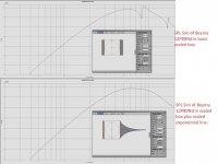
Leonard Audio has a thread discussing their free "Transmission Line" simulator. The dark shaded areas in the box model represent different densities of absorption material.
The Beyma 12P80Ndv2 is typically used as a high efficiency midbass which is "controlled directivity" mated to a horn-tweeter or AMT-tweeter at crossover frequencies from 1200-1600Hz. A woofer is used from ~180Hz (baffle step) down to 25-30Hz. Cabinets which remove high frequency resonances with the lowest coloration seem worth consideration with these designs. S-M-O-O-T-H like Miles D.
LewinskiH01 desires to use a sealed 12P80Nd from 80-450Hz, which I do not think is possible... Qts=0.15 midbass cannot reach -3db @80Hz even with a large 1/2 wavelength long open end TL.
With equalisation a lower crossover frequency should be achievable, like I am proposing to use with a oversized sealed cabinet. Following this thread with interest, its suggesting that the TTL may be worth considering. I have some thoughts of a cornu style TL if this approach is the way to go.
Leonard Audio has a thread discussing their free "Transmission Line" simulator. The dark shaded areas in the box model represent different densities of absorption material.
The Beyma 12P80Ndv2 is typically used as a high efficiency midbass which is "controlled directivity" mated to a horn-tweeter or AMT-tweeter at crossover frequencies from 1200-1600Hz. A woofer is used from ~180Hz (baffle step) down to 25-30Hz. Cabinets which remove high frequency resonances with the lowest coloration seem worth consideration with these designs. S-M-O-O-T-H like Miles D.
LewinskiH01 desires to use a sealed 12P80Nd from 80-450Hz, which I do not think is possible... Qts=0.15 midbass cannot reach -3db @80Hz even with a large 1/2 wavelength long open end TL.
I do believe Mr. Lewinski has finally settled on using 2 units per side of the Beyma 10G40's.
its suggesting that the TTL may be worth considering.
TTL at 450 Hz? Maybe if it's with a steep XO at the tap point.
GM
Leonard Audio has a thread discussing their free "Transmission Line" simulator. The dark shaded areas in the box model represent different densities of absorption material.
The Beyma 12P80Ndv2 is typically used as a high efficiency midbass which is "controlled directivity" mated to a horn-tweeter or AMT-tweeter at crossover frequencies from 1200-1600Hz. A woofer is used from ~180Hz (baffle step) down to 25-30Hz. Cabinets which remove high frequency resonances with the lowest coloration seem worth consideration with these designs. S-M-O-O-T-H like Miles D.
LewinskiH01 desires to use a sealed 12P80Nd from 80-450Hz, which I do not think is possible... Qts=0.15 midbass cannot reach -3db @80Hz even with a large 1/2 wavelength long open end TL.
Sorry guys I've been unable to connect for a couple of days.
Thanks Linesource for joining in. I will look into the Leonard Audio thread.
As great as the 12P80Nd is as a driver, I'm coming to the conclusion is not the best fit for my needs. At the top end, its directivity is not ideal to match a TPL-150H at around 2kHz and I'm leaning towards an 8" midrange. At the low end it doesn't seem to get low enough to meet the subwoofers at 80hz. Angeloitacare is using this driver and claims excellent results at both extremes, though.
As Scott mentioned, right now I'm leaning towards two 10G40 per side to run 80-450Hz (approx), for these reasons:
- Two midbass drivers seem to allow for better placement to compensate baffle step loss, floor reinforcement, etc (smoother frequency response around the baffle step).
- Only needs 25Wpc to achieve 105dB at 80Hz and F-3dB of 121Hz in a box with Qtc=0.707
- One of the lowest Le (0.6) and one of the lowest Bl/Mms (3.1).
- 2nd highest Vd @ 80Hz and 105dB (so in my book, bigger sense of impact)
- While keeping displacement under 20% of Xmax at all times (so lower distortion)
- Sensitivity of 100dB (close to tweeter at 102dB and midrange in the neighborhood of 100dB)
Beyond my earlier explanation, I can't think of a way to dumb it down further other than to say that it's designed to flatten the driver's impedance spike at tuning [Fp]: http://www.diyaudio.com/forums/mult...-transmission-line-midbass-2.html#post4402349
GM
Not being a native English speaker sometimes is a challenge at fora. Other times it's somewhat frustrating to explain English terms to a native English speaker.
You say you can't think of a way to dumb it down further, and dumb it down means to make it dumber in a way less intelligent people can understand.
But I asked if you could restate in layman terms, which means using plain language that avoids jargon known by those within the art.
Far from dumb, I'm considered a highly intelligent professional with a few degrees, including two in engineering. Yet I'm new to speaker design, so I'm not familiar with its jargon.
Over the years I've noticed those with highest degree of knowledge and conceptual clarity are often able to better explain complex concepts in layman terms. The flip side is oftentimes those who keep cover behind jargon simply aren't clear enough in their minds to explain it in other terms.
Not a big deal, though. I'll get around jargon and figure out if there is any merit to what I thought of doing.
- Home
- Loudspeakers
- Multi-Way
- Terminated transmission line for midbass?