In "reading between the lines" it seems you're definition of what a real TL is old hat and means a long, non-tapered line which has literally had the life stuffed out of it so that it behaves like a large sealed box, having a single impedance peak and a 2nd-order bass rolloff. All TLs, since they have an open end, are inherently 4th-order systems like a vented or BR enclosure. Stuffing them to make them appear to not be 4th-order systems only eliminates all output from their terminus, or port if mass-loaded, thus throwing away all bass support. Why would one want to do that?😕
Paul
Paul
By the way, what is commonly called a transmission-line loudspeaker, in my book really isn't. It's a badly terminated transmission-line at best, which I'd rather call a tuned resonator. In that sense it is actually similar to a bass-reflex loudspeaker.
Why would one want to do that?
Paul, when using the box as a midTL. You just want the back wave to dissappear. I would describe it as stuffed until aperiodic, the remaining peak is smaller than you would expect in a sealed box.
But in a regular TL, that is the definition of a TL mis-taken from the Bailey article title, not what he actually built and showed off in the article.
dave
I was pointed to the Martin King work, which I found and have pending to read. Probably this weekend.
But help me make sure I'm understanding the very basics right. The above conversation isn't clear to me if it refers to a TL with an opening at the end of the line or a sealed box. My rationale is a sealed box is "faster" for midbass and I plan to build that.
An improvement over a "regular" sealed box (could be irregularly sized, even a pentagon footprint to minimize reflections) would be a TL because of the elimination of the backwave.
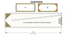
A TL works with 1/2 wavelengths, so the lower I want to use it the longer the needed TL. If I want to make sure the backwave of an 80Hz signal is not reflected then the length of the TL needs to be at least 215cm. If the XO is to be set at 80Hz and assuming a 24 dB/octave slope, what's a good practice for the design? Should I make sure a 40Hz signal isn't goint to get reflected, so I should use a 430cm long TL?
How much influence does the shape of the section of the TL matter? Section with 90 degree angles vs rounded internal angles vs round section?
Attachments
Dave, I understand clearly what this specific thread was about, the mid TL and its purpose, but Keyster was making a comment about TLs in general as if they don't or can't work well, which you and I and others know is wrong. At least that was my impression of his comments. If I misconstrued his meaning, he can "splain" it to me.
Paul
Paul
Paul, when using the box as a midTL. You just want the back wave to dissappear. I would describe it as stuffed until aperiodic, the remaining peak is smaller than you would expect in a sealed box.
But in a regular TL, that is the definition of a TL mis-taken from the Bailey article title, not what he actually built and showed off in the article.
dave
Traditionally a transmission-line is considered to be a conduit used to carry an AC signal from one location to another. This is of great importance for the design of radio technology, long distance communication and computer hardware.
At high frequencies and greater transmission distances, wavelengths have dimensions that are approaching or even smaller than the length of the transmission-line. If the transmission-line is not well-designed, there will be reflections in the transmission-line. The key here is impedance-matching. The output impedance, input impedance and the characteristic impedance of the transmission-line have to match, so that energy is effectively transferred and there are no reflections in the transmission-line.
The closest parallel in acoustics probably is an impedance tube, or plain wave tube. Sound comes in on one end, encountering damping material of gradually increasing density. The result ideally is complete absorption of the acoustic energy, without reflection due to acoustic impedance mismatching inside the tube. This is the kind of thing B&W tried to do with their lovely Nautilus loudspeakers.
What is confusingly called a transmission-line loudspeaker, doesn't really have anything to do with what is traditionally considered to be a transmission-line. The goal is not the transmission of a signal from one end to the other, it rather is to excite a pipe-resonance that is used to increase the output and to extend the lower frequency limit of a loudspeaker. I am not saying the technique doesn't work. What I'm saying is that a transmission-line loudspeaker and a plain wave tube really are two different things. Let's not confuse the two.
Thank you. That was a good explanation, very helpful to me.
My goal in considering a transmission line is not to extend the lower end nor increase the output of the drivers. I was viewing it as a way to improve sound...a vague term I know...thinking of lowering distortion generated by the back wave reflection.
It is a good idea to use a TL in a sealed cabinet if this is my goal? Would the schematics I included in my earlier post today achieve this?
My rationale is a sealed box is "faster" for midbass and I plan to build that.
All faster means is that it has better HF performance. A fully aperiodic line is, as Paul alluded, essentially sealed -- but better, low pressure, lower impedance peak.
An improvement over a "regular" sealed box (could be irregularly sized, even a pentagon footprint to minimize reflections) would be a TL because of the elimination of the backwave.
Yes.
A TL works with 1/2 wavelengths
A sealed TL.
How much influence does the shape of the section of the TL matter? Section with 90 degree angles vs rounded internal angles vs round section?
The taper has an effect, high taper means a shorter line. Cross section only really if the dimensions approach that of any signal in the bandwidth of the speaker. Smoothing the line is actually counterproductive.
dave
but Keyster was making a comment about TLs in general as if they don't or can't work well, which you and I and others know is wrong.
I'm pretty sure you got that right. The second sentence pointed to that.
King and, to a lesser extent, Augspurger, opened up huge new areas of TL design space, whereas there is a small group of people who think a TL is only a small area loosly fitting into that defined by mis-understanding the title of Bailey's article. I have run into those before.
dave
... called a transmission-line loudspeaker, doesn't really have anything to do with what is traditionally considered to be a transmission-line…
True. Get over it.
dave
Thanks for reiterating what I learned, leading up to receiving my BSEE, over 50 years ago.🙄 It seems you're mostly upset with semantics.
Paul
Paul
Traditionally a transmission-line is considered to be a conduit used to carry an AC signal from one location to another. This is of great importance for the design of radio technology, long distance communication and computer hardware.
At high frequencies and greater transmission distances, wavelengths have dimensions that are approaching or even smaller than the length of the transmission-line. If the transmission-line is not well-designed, there will be reflections in the transmission-line. The key here is impedance-matching. The output impedance, input impedance and the characteristic impedance of the transmission-line have to match, so that energy is effectively transferred and there are no reflections in the transmission-line.
The closest parallel in acoustics probably is an impedance tube, or plain wave tube. Sound comes in on one end, encountering damping material of gradually increasing density. The result ideally is complete absorption of the acoustic energy, without reflection due to acoustic impedance mismatching inside the tube. This is the kind of thing B&W tried to do with their lovely Nautilus loudspeakers.
What is confusingly called a transmission-line loudspeaker, doesn't really have anything to do with what is traditionally considered to be a transmission-line. The goal is not the transmission of a signal from one end to the other, it rather is to excite a pipe-resonance that is used to increase the output and to extend the lower frequency limit of a loudspeaker. I am not saying the technique doesn't work. What I'm saying is that a transmission-line loudspeaker and a plain wave tube really are two different things. Let's not confuse the two.
All faster means is that it has better HF performance. A fully aperiodic line is, as Paul alluded, essentially sealed -- but better, low pressure, lower impedance peak.
Great. All good news.
I need some clarification due to languaje: what is higher taper? Say a rectangular cross section of 10x6, that tapes 100cm later to 10x2. Does that have a higher or lower taper than 10x6 taping 60cm later to 10x2?The taper has an effect, high taper means a shorter line.
Should the range be 80-450Hz, at 450 the 1/2 wave is 38cm long. My initial draft of the baffle is about 35cm external and 27cm internal width. Is 27cm far enough?Cross section only really if the dimensions approach that of any signal in the bandwidth of the speaker.
Why is this so? It is counterintuitive to me, but I admit I know nothing about this.Smoothing the line is actually counterproductive.
dave
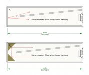
In the example below:
On A) part of the sound coming from the driver would bounce back into line and part would go back to the driver. I realize sound arriving perpendicular into the surface will bounce back perpendicularly too, but I graphed it that way to illustrate the point.
On B) the sound bounces into a deflector that sends it into the line.
I'm not claiming to be correct. Just explaining my rationale so you can point me were my misconception is. It's my way of learning!
Attachments
I need some clarification due to languaje: what is higher taper?
In this case taper is smaller at the terminus than at the start. I use ~10:1 for high taper, Paul uses even more.
Should the range be 80-450Hz, at 450 the 1/2 wave is 38cm long.
You are only interetested in the lowest frequency. If going sealed you need a volume sufficient to give the sealed response you want. A 1/4 wl line likely needs to be bigger.
Why is this so? It is counterintuitive to me, but I admit I know nothing about this.
At the frequencies involved the little arrows are meaningless. The long sound waves do not see the reflectors. If there are no reflectors, there is a small expansion in the cross-section of the box at the fold that acts as a high-pass filter. In horns it can be important, in a heavily stuffed TL it is probably closer to just theoretically important.
dave
I believe you mean 'low' pass filter. 😉 Right, it just means more volume available to add stuffing to.
GM
GM
I believe you mean 'low' pass filter.
Yes Greg, thanx for the correction.
dave
I need some clarification due to languaje: what is higher taper? Say a rectangular cross section of 10x6, that tapes 100cm later to 10x2. Does that have a higher or lower taper than 10x6 taping 60cm later to 10x2?
To elaborate a little........
If a constant [zero] taper, i.e. a simple pipe = 1:1, then a positive [horn] taper of 2x = 1:2 and an inverse [TQWT] taper of 2x = 2:1, so both a 1:10 and 10:1 is a high taper regardless of length and as Dave noted, the greater the taper the more it affects the acoustic path-length, with it being longer for a horn and shorter for a TQWT referenced to a zero taper.
GM
Last edited:
One other factor - speed of sound is slower in stuffed lines, making the half wavelengths lower frequency (for a given length).
Also has anybody looked at line termination (thinking vario-vent or a small stuffed opening). Theoretically a proper termination would give no reflection and look like an infinite line (but radiating sound).
Also has anybody looked at line termination (thinking vario-vent or a small stuffed opening). Theoretically a proper termination would give no reflection and look like an infinite line (but radiating sound).
One other factor - speed of sound is slower in stuffed lines
That is pretty much a myth.
dave
That is pretty much a myth.
dave
Is it -from wikipedia https://en.wikipedia.org/wiki/Acoustic_transmission_line
The introduction of the absorption materials reduces the velocity of sound through the line, as discovered by Bailey in his original work. L Bradbury published his extensive tests to determine this effect in an AES Journal in 1976 [3] and his results agreed that heavily damped lines could reduce the velocity of sound by as much as 50%, although 35% is typical in medium damped lines.
Last edited:
Bradbury's work is questionable. Actual experimental evidence shows insignificant slow down.
dave
dave
OK From Pearls from Martin J King Quarter Wave Design
I just needed some kind of authentification rather than flat dismissalSpeed of sound in a stuffed line -- The TL resonates at one quarter of the wavelength of the frequency set as the tuning point. The wave length depends on the speed of sound. Damping of the pipe will slow down the speed of sound a little, and since the wave length depends on the speed of sound, a slight lowering of the tuning frequency will occur. However, this is not a dramatically reduction at all. A couple of Hz is what you will gain at the most. It is very difficult even to be able to measure if the tuning frequency has changed, as the impedance curve is damped and flat. Your local altitude and the temperature of the air has more of an impact on the tuning frequency than the stuffing..
Last edited:
- Home
- Loudspeakers
- Multi-Way
- Terminated transmission line for midbass?