Just got back from another gig, and will be crashing into bed shortly.
Used a single cab in a 150-cap venue. Some seated, some standing. Driven with one side of the MA12000i for around 2.2KW into the 8ohm nominal impedance.
More than enough to feel the beat for rock 'n' roll. Towards the end, I pushed up the bass and kick faders, and it just kept putting out more low end. When I checked, I still wasn't clipping the amplifier!
If I wanted it much louder overall, I would've needed to fully mic the (loud!) drummer.
That cab really didn't have any right to do what it did this evening. I'm very pleased. The size-to-output ratio is excellent.
Chris
Is there any way we could see the finished product again please ? The pictures don't seem to show up for me unless I'm doing something wrong ?
With repeated tests, the notch in cone output showed up at 30Hz every time. Doesn't fit with the impedance curve, doesn't fit with port output. I can see that.
I ran into this with my POC6 build.
I eventually surmised that this is a really crappy way to determine Fb, because at the point at which the driver is doing minimum excursion (and SPL output), SPL output from the vent is at or near maximum, and the mic will be picking up the sound from the vent as well.
Impedance measurement and looking for when the phase crosses zero is the best method.
Impedance measurement and looking for when the phase crosses zero is the best method.
I agree.
I ran into this with my POC6 build.
I eventually surmised that this is a really crappy way to determine Fb, because at the point at which the driver is doing minimum excursion (and SPL output), SPL output from the vent is at or near maximum, and the mic will be picking up the sound from the vent as well.
Impedance measurement and looking for when the phase crosses zero is the best method.
I made a seperate thread about it, but photobucket ate the pictures when it decided it didn't want any users any more.
The TL;DR is that by changing the mic position on the cone, I could get a null anywhere from 25Hz up to 38Hz. Actual tuning came out somewhere around 39Hz.
Picture from a gig last year -

I'm really happy with these subs. Last night was 200 people seated in a village hall. There was punch at the back, 20m away, with two subs.
The MA12000i does help with that.
Chris
The TL;DR is that by changing the mic position on the cone, I could get a null anywhere from 25Hz up to 38Hz. Actual tuning came out somewhere around 39Hz.
Yup, that's falls in line with my hypothesis - as the mic is shifted closer to the vent, I bet that the "null" moves further away from Fb.
I'm really happy with these subs. Last night was 200 people seated in a village hall. There was punch at the back, 20m away, with two subs.
Those do look like a nice build. Have you ever done any linearity testing with them? Basically measure the response to short sine sweeps while upping the input voltage in small steps (I use 3dB, then smaller as I get close to theoretical linear limits, or the subwoofer is starting to audibly complain).
Yup, that's falls in line with my hypothesis - as the mic is shifted closer to the vent, I bet that the "null" moves further away from Fb.
Yep, that's it exactly. In the end, I learnt not to trust that method.
Those do look like a nice build. Have you ever done any linearity testing with them? Basically measure the response to short sine sweeps while upping the input voltage in small steps (I use 3dB, then smaller as I get close to theoretical linear limits, or the subwoofer is starting to audibly complain).
I went back over the REW files, and it turned out I'd done some linearity testing apart from when I folded the cone.
Up until I clipped the NU6000, there wasn't anything to show. The level differences were quite course, though, so if I'd done 1dB increments something might've shown.
When the amp clipped, the level of the overall sweep dropped by 2dB. At 40Hz, the difference is 4dB. So I'd say there's 2dB of compression at 40Hz at around 90v sine wave input.
I also tried a 30Hz vs 36Hz BW4 filter, and found there wasn't anything to be gained by setting it lower - there was just more distortion at 30Hz.
The distortion curves show a spike at 100Hz, which could be room-related since the test was indoors. Away from that, still at full power from the NU6000, distortion stays around 15% THD, dominated by 2nd and 3rd harmonics - 4th and 5th harmonics were 1/10th the level of 2nd and 3rd.
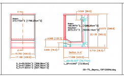
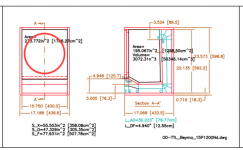
Test driver was one of the Beyma 15P1200Nd units.
I might try bridging the MA12000i to see what these cabs can really do, but I want to avoid folding the cones again.
Edit - and I don't really want to find that an MA12000i bridged into each cabinet is what it really takes for them to come alive, because then I'd need 7 more of them!
Chris
Last edited:
Page 12, at the top. I went for the 3-panel port option, which increases the internal volume a little.
Chris
Chris
Page 12, at the top. I went for the 3-panel port option, which increases the internal volume a little.
Chris
But we are on page 5, what's the post #?
Dan, looks like we are (were) on page 15 on my screen ;^).But we are on page 5, what's the post #?
Top of "page 12" In post #111, Oliver has posted Hornresp inputs and response curves, and a link to a long and longer port drawing, the "3 panel port" pictured on the right.
Chris might link it in the OP, I went through all 15 pages earlier today and missed it, even after following the thread the first time around...
Art
Attachments
lol
sorry for the silly question but
i have seen pretty detailed drawings over here with 3d images and all
this is was just 2 diagrams
so i center the hole and hit it
also, almost all of the attached pics in the thread are gone
does somebody salvaged a respose graph ?
and suggested processor parameters as HP LP
and any corrective EQ
also, does the DEQ2496 spit over the driverack pa ?
i have seen almost anybody use the 2496 over the driverack pa
It seems a RCF LF15X401 might work well in this box. When playing in Hornresp, I came up with something similar, a long port BR of similar size. And a pair of these should fit into my car🙂 Is there any advantage compared to a more traditional BR layout?
Edit: I was too quick. This looks like a traditional BR actually. I have another question - if I understand it correctly, the front baffle is two layers, is that right? I need to check if the RCF will fit in, maybe with small modifications. I really like this box style.
Edit: I was too quick. This looks like a traditional BR actually. I have another question - if I understand it correctly, the front baffle is two layers, is that right? I need to check if the RCF will fit in, maybe with small modifications. I really like this box style.
Last edited:
- Home
- Loudspeakers
- Subwoofers
- Teeny tiny PA 15" subwoofer