Pass DIY Addict
Joined 2000
Paid Member
Have you mounted the SMPS internally or externally? An external mount provides some additional flexibility in placement of both the PSU and the cabling. Shielded cables will also help. I know that some have reported good results with SMPS supplies, particularly the Meanwell ones. I don't like them (for exactly the reasons you posted), so I tend to stick with linear supplies.
Pass DIY Addict
Joined 2000
Paid Member
Take your time and be methodical in your approach and I'm sure you'll be able to solve the hum. It may be necessary to install some shielding, either for the wire or the PSU itself. You might get away with just moving wires around.
I'm following this thread because I plan to install I meanwell PS, internally. I mean inside the technics 🙂
Which meanwell model did you use?
Which meanwell model did you use?
I did use the RS-15-24
I will get a balanced riaa and either swap the cables or the contacts. I am lookint at the Musical Fidelity MX-VYNL.
I will get a balanced riaa and either swap the cables or the contacts. I am lookint at the Musical Fidelity MX-VYNL.
Ciao a Tutti!
Thanks to Jim's supe-tutorial (thanks! ) next month I'll move my 1210 PTX to an external case and make a crcrc PS. As I have European transformer, I'll also try the snubber measured with Quasimodo. I also like to change Q1 with a modern UWB, and I thought to Belleson SPX78 (SPX Max Performance), but looking at the datasheet I noted that they're rated 35V as VMax: would it be necessary to reduce DC at its input? Maybe increasing R values on PSU?
Cheers from Milan,
Vincenzo
Thanks to Jim's supe-tutorial (thanks!
) next month I'll move my 1210 PTX to an external case and make a crcrc PS. As I have European transformer, I'll also try the snubber measured with Quasimodo. I also like to change Q1 with a modern UWB, and I thought to Belleson SPX78 (SPX Max Performance), but looking at the datasheet I noted that they're rated 35V as VMax: would it be necessary to reduce DC at its input? Maybe increasing R values on PSU?Cheers from Milan,
Vincenzo
Attachments
Pass DIY Addict
Joined 2000
Paid Member
My notes show that I measured 30.9vAC out of the original stock transformer (US version intended for 120v mains). Rectifying this results in a linear power supply that is near 42-43vDC. This is clearly too much input for the regulator you have chosen that indicates a max input of 35v.
You can still use the regulator that you chose - you'll need to implement CRC or maybe CRCRC and adjust the resistor values to drop the voltage down so you don't burn up your regulator. I used a CRCRC with 10R 3w resistors. Each resistor drops a few volts, so I have a DC power supply of 32.4v out of the final cap before the internal regulators that I added. This should meet your needs. The particular resistors that I used reach about 42c in this situation.
If you are interested in using such nice and small regulators, you can go another step and install two of them in the hole left by removing the transformer. One of them will be for motor drive (higher current draw) and the other will be for the motor control logic circuit (lower current draw). This necessitates cutting a trace on the bottom of the PCB - no big deal if you're already comfortable installing regulators. Don't know that I can actually *hear* a difference because I separated these functions, but it was a fun little project.
I have some images of the regulators I made and images of how they were installed is down about 5 more posts.
Last edited:
I did use the RS-15-24
I will get a balanced riaa and either swap the cables or the contacts. I am lookint at the Musical Fidelity MX-VYNL.
Yesterday I hooked up a balanced riaa. It worked but I had some low volume noise at 50% of volume control. When I wanted to do some more checks this morning it was dead.
I disconnected the 24V+ of the SMPS and put in a new 250 mA fuse on the primary side. It blew within a second. So the MeanWell SMPS is gone. Hopefully it didn´t bring the motherboard with it. The secondary side fuse is intact.
I don't remember if I left the player on or off yesterday.
Mårten
Tonight I successfully connected an external SMPS with PFC. There is no hum or noise from the Technics.
I believe I will build an external power supply. I dont trust the RS-15-24 any more.
There was a static discharge when I touched the Technics. This should be handled by proper grounding. Should I ground through the power supply or through the riaa?
Mårten
I believe I will build an external power supply. I dont trust the RS-15-24 any more.
There was a static discharge when I touched the Technics. This should be handled by proper grounding. Should I ground through the power supply or through the riaa?
Mårten
Last edited:
So, here we are 😄 First of all, many thanks to 6L6 for the tutorial 👍
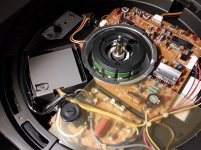
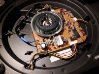
I started obviously by removing the internal PSU.
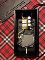
I found a cheap PCB for double pi filter and I used 4x22 ohm 5W ceramic resistors. Quasimodo snubber (European tranny) is placed under the board and 3x3300uF caps used in crcrc.
I started obviously by removing the internal PSU.
I found a cheap PCB for double pi filter and I used 4x22 ohm 5W ceramic resistors. Quasimodo snubber (European tranny) is placed under the board and 3x3300uF caps used in crcrc.
Some pics...
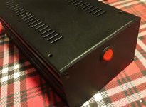
I used the original on/off switch for strobe.
I used the original on/off switch for strobe.
Attachments
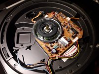
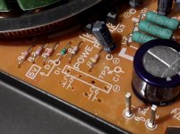


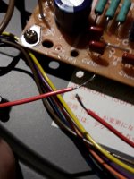
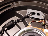
Removed bridge and snubber caps, placed new umbilical and soldered switch wires to strobe.
Attachments
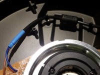

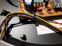
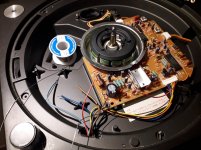
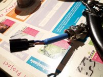
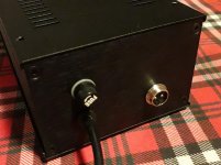
New cable holder on original bracket and Mike 2 pin connector for the umbilical. Now waiting for a Galaxy 2 units cabinet 😃🖖
Attachments


Last edited:


Just a question: as I used a metal cabinet, does I have to connect it to the ground? And in that case, how can I avoid the risk of ground loop with the earth? Thanks in advance
- Home
- Source & Line
- Analogue Source
- Technics SL-1200 DC Power Supply