I know the area around the main transistors well.
When I bought the A3, two DLP transistors were already burnt. At that time, I replaced only two DLPs with new ones — old stock. That’s why I bought three pieces back then.
Later, when I took the amplifier to a technician to adjust the bias current (ICQ) and everything else related, a problem appeared with the power board that controls the transistors. The DLPs burned out again because the technician applied too much voltage at once to the amplifier.
I got frustrated and removed everything.
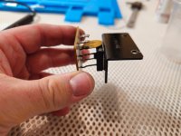
Now, I have brand-new, very rare Toshiba transistors installed — 2SC5359 and 2SA1987 — with excellent hFE values. These were typically used by the Japanese in their A3 models.
When I bought the A3, two DLP transistors were already burnt. At that time, I replaced only two DLPs with new ones — old stock. That’s why I bought three pieces back then.
Later, when I took the amplifier to a technician to adjust the bias current (ICQ) and everything else related, a problem appeared with the power board that controls the transistors. The DLPs burned out again because the technician applied too much voltage at once to the amplifier.
I got frustrated and removed everything.
Now, I have brand-new, very rare Toshiba transistors installed — 2SC5359 and 2SA1987 — with excellent hFE values. These were typically used by the Japanese in their A3 models.
The amplifier is still not finished. You have the video and pictures.
So,
I have a problem... I recently visited a technician who has all the necessary instruments to properly adjust amplifiers, distortion analysis, etc...
Basically, although the amplifier works, it doesn't function correctly. Specifically, on an 8-ohm load it reaches 200W without clipping — that's fine.
However, there's some sort of distortion — the 3rd harmonic has an elevated amplitude. The clamp trimmer doesn't respond — neither on the left channel nor the right.
When we turned it, as per the manual instructions, nothing happened. The distortion remained the same.
Later, we discovered that the clamp trimmer actually affects the bias current. When turning the clamp trimmer — surprise — the bias increases.
But we can’t lower the bias under 40 mV per transistor when the amp is warmed up.
Increasing it is somewhat possible though.
The second, and even more serious issue, is that at 4 ohms, distortion starts appearing at around 25W output.
We noticed this with the technician using his equipment, and I’m observing the same at home.
At 25W into 4 ohms, a waveform deformation appears — some sort of distortion.
What could be causing this strange behavior?
Has anyone had a similar issue? I don’t know what else to do anymore…
Which component should I check?
Attachments

The distortion you see is nothing to do with bias current, something else is going on.
You say both channels are the same, I would begin by looking at all the rails to all boards with the scope and see if anything show up there. It seems unlikely both boards would have a similar fault.
If you have changed the same components on both channels then something common may be wrong there. Very difficult at a distance to diagnose.
No. I only touched and repaired the left driver board… I didn’t touch the right one. Just fix the bad solder joints on it, not everywhere.
On the left board, there were two burnt 120-ohm resistors that I replaced.
On the right board, nothing was burnt.
Yes, the issue appears the same on both channels.
I tried completely disabling one channel and testing at 4 ohms, but the situation is the same.
How do you check the rails?
Oh, one more thing… on the left and right DC boards — the ones located behind the driver boards — I replaced the 82kOhm resistors because they were showing incorrect values. Some were even reading in the mega-ohms.
Thanks.
On the right board, nothing was burnt.
Yes, the issue appears the same on both channels.
So you have to look at what is common to both... PSU's
Oh, one more thing… on the left and right DC boards — the ones located behind the driver boards — I replaced the 82kOhm resistors because they were showing incorrect values. Some were even reading in the mega-ohms.
Were these checked out of circuit? Sometimes diagrams have different values to what is fitted due to production changes. If those are the only thing you changed on the good board then you have to look at whether an incorrect value is a possibility.
You need to locate all the rails that feed the different sections of the amp such as front end, driver stages, output stages and so on and then both measure the DC values and also use the scope to see if anything odd is happening such as a rail dropping under load and having excess noise or ripple.How do you check the rails?
How is someone supposed to know?? If the service manual said it should be 82kOhm, then I replaced them. Now I honestly don’t remember what the original values were — not even if you gave me a million euros.
The amplifier is Japanese, 100V. Maybe something really is wrong… I’ll have to find the old resistors in the trash.
I replaced 3 or 4 on each side.
I read on the forum here that everyone replaces those 82kOhm resistors on the DC boards…
I measured the components desoldered.
The amplifier is Japanese, 100V. Maybe something really is wrong… I’ll have to find the old resistors in the trash.
I replaced 3 or 4 on each side.
I read on the forum here that everyone replaces those 82kOhm resistors on the DC boards…
I measured the components desoldered.

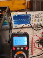
If that scope shot is showing the input (the generator output) then something is effectively modulating that signal. Ground problems maybe. Impossible to say what is going on without seeing it for real.
Don't lose sight of the fact that you originally had a problem on only one channel.
Don't lose sight of the fact that you originally had a problem on only one channel.
Is it possible that the bias diodes are faulty? The four of them, arranged in two pairs on the driver board? Or do they have nothing to do with the issue I'm experiencing?
Its unlikely seeing as you have both channels with the same fault.
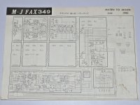
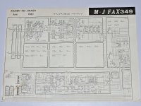
I can't come up with a full and readable circuit for this. There also seems to be two versions of this amp.
I can't come up with a full and readable circuit for this. There also seems to be two versions of this amp.
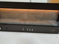
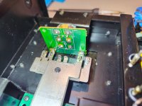
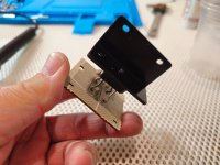
That's right. In Japan, they sold the version I have, which is 100V, and near the main capacitors there's a small circuit board. As you can see in the picture, it has one rectifier and one thermistor. The European version has all sorts of components crammed in there. The Japanese built a different version specifically for their 100V market.
However, there's no manual to be found anywhere.
I would like to buy the manual — I’m willing to pay 50€ if necessary — but I can’t find it anywhere. How is that even possible? Should I write to some Japanese technician?
However, there's no manual to be found anywhere.
I would like to buy the manual — I’m willing to pay 50€ if necessary — but I can’t find it anywhere. How is that even possible? Should I write to some Japanese technician?
Attachments
Only you can answer that on getting a manual 🙂
The distortion you show actually looks like it might be some form of current limiting coming into play.
1/ Does the distortion disappear if you remove the load?
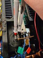
2/ Try removing these two diodes and see if things improve.

The distortion you show actually looks like it might be some form of current limiting coming into play.
1/ Does the distortion disappear if you remove the load?
2/ Try removing these two diodes and see if things improve.

Are you sure it won’t cause any issues if I desolder them?Only you can answer that on getting a manual 🙂
The distortion you show actually looks like it might be some form of current limiting coming into play.
1/ Does the distortion disappear if you remove the load?
2/ Try removing these two diodes and see if things improve.
View attachment 1449503
Is there anything I should be careful about when powering it on?
Should I monitor the bias as I go?
Should I power it on through a variac (variable transformer)?
Where exactly do I measure the voltage once I disconnect those diodes?
Thanks.
Are you sure it won’t cause any issues if I desolder them?
I wouldn't mess with the bias diodes but I'm not an expert either.
After I measure the PSU voltages everywhere I would follow the signal to see where it does get distorted. Is it in the preamp, driver board or elsewhere?
Are you sure it won’t cause any issues if I desolder them?
They look to be a standard way of connecting the over current protection to the driver stages. Normally they do nothing and the transistors that drive them (Q130 and Q131) also normally do nothing.
Having said that there are no guarantees but given the amp works and you have little to no bias current I can't see any issue.
Where exactly do I measure the voltage once I disconnect those diodes?
You just see if you can get past that point you showed on the scope where distortion set in. Does the lifting the diodes remove that distortion and allow more output.
- Home
- Amplifiers
- Solid State
- Technics SE-A3 bias adjustment