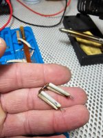
The resistors R154 and R157 do not show 120 ohms, but one shows 4 MΩ, while the other is completely open. They are fuse-type carbon resistors.
Is it still possible to find them? Or should I use a standard 120-ohm carbon resistor 5% tolerance, 1/2W?
Any advice?
Is it still possible to find them? Or should I use a standard 120-ohm carbon resistor 5% tolerance, 1/2W?
Any advice?
Attachments

So, after replacing the 120-ohm resistors, the situation remains unchanged... I temporarily installed 120-ohm metal oxide 1% resistors until I order 120-ohm carbon 2%. I'm not sure if fuse resistors exist anywhere...
Now to explain:
I moved the driver board from the right channel to the left side to check if the issue was with the left driver board... and guess what... the problem is with the board. The left side lifted, and the bias was around 0.60 millivolts.
I moved the faulty board to the right channel, and it didn’t work there either.
So, the issue is with the driver board.
I replaced the two 120-ohm resistors because they were open and reflowed the cold solder joints.
I measured all the components that could be measured, using a regular multimeter. The rest, the resistors and diodes, are all fine... I measured the transistors in diode mode, and none showed signs of being open or in short-circuit.
I carefully reassembled everything back into the case and connected the faulty board to the left channel. I used a variac (a variable transformer) to monitor the situation.
The amplifier is a 100V Japanese model.
I measured the bias on both the left and right channels.
As I slowly increased the input voltage, somewhere around 45V, the bias on the left channel jumped to 200 millivolts, while the right channel remained steady at 0.7 millivolts.
I didn’t want to go beyond this value, as I’m afraid of burning out the main power transistors.
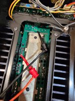
I suspect that the four transistors mounted on the heatsink on the driver board are the cause.
What do you think?
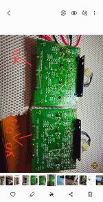
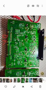
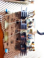
Below are some pictures...
The boards are a bit rough in certain spots, but I measured everything carefully, and everything seems fine.
Picture:
Now to explain:
I moved the driver board from the right channel to the left side to check if the issue was with the left driver board... and guess what... the problem is with the board. The left side lifted, and the bias was around 0.60 millivolts.
I moved the faulty board to the right channel, and it didn’t work there either.
So, the issue is with the driver board.
I replaced the two 120-ohm resistors because they were open and reflowed the cold solder joints.
I measured all the components that could be measured, using a regular multimeter. The rest, the resistors and diodes, are all fine... I measured the transistors in diode mode, and none showed signs of being open or in short-circuit.
I carefully reassembled everything back into the case and connected the faulty board to the left channel. I used a variac (a variable transformer) to monitor the situation.
The amplifier is a 100V Japanese model.
I measured the bias on both the left and right channels.
As I slowly increased the input voltage, somewhere around 45V, the bias on the left channel jumped to 200 millivolts, while the right channel remained steady at 0.7 millivolts.
I didn’t want to go beyond this value, as I’m afraid of burning out the main power transistors.
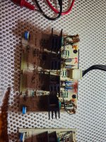
I suspect that the four transistors mounted on the heatsink on the driver board are the cause.
What do you think?
Below are some pictures...
The boards are a bit rough in certain spots, but I measured everything carefully, and everything seems fine.
Picture:
Attachments
-
 20250409_014522.jpg650.1 KB · Views: 36
 -
 Screenshot_20250409_023045_Gallery.jpg433.5 KB · Views: 39
 -
 Screenshot_20250409_023110_Gallery.jpg388 KB · Views: 37
 -
 Screenshot_20250409_023128_Gallery.jpg378.2 KB · Views: 37
 -
 20250409_011323.jpg629.6 KB · Views: 35
 -
 20250409_011335.jpg464.4 KB · Views: 36
I would definitely measure the transistors on the driver board more closely.
(Remove the transistors and then measure again!)
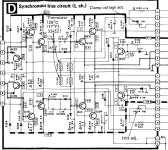
Check D111, D112, D110, D113 !!
(Remove the transistors and then measure again!)
Check D111, D112, D110, D113 !!
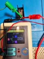
I measured diodes D111, D112, D110, D113.
D110 shows 0.387 on the multimeter.
D113: 0.396
D111: 0.404
D112: 0.380
I measured the diodes on the board. I didn't desolder them.
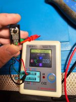
Transistors Q123, Q122, Q121, Q124, Q131, Q130 are all fine. Here are the pictures...
Only diode D113, when I reverse the probes with the multimeter, shows 2.653.
On the other diodes, when I reverse the probes, nothing shows.
D110 shows 0.387 on the multimeter.
D113: 0.396
D111: 0.404
D112: 0.380
I measured the diodes on the board. I didn't desolder them.
Transistors Q123, Q122, Q121, Q124, Q131, Q130 are all fine. Here are the pictures...
Only diode D113, when I reverse the probes with the multimeter, shows 2.653.
On the other diodes, when I reverse the probes, nothing shows.
Attachments

Last edited:


Did you try what I suggested in post #20?
Tis is my video whit osciloscope
Last edited:
That does seem to show some kind of instability (the spikes superimposed onto what seems to be a lower fundamental frequency. The fundamental looks to be mains related (50 or 60 Hz). I'm assuming the good channel is clean. Those spikes are actually still very low frequency in the scheme of things.
It would be worth looking at the input to the amp on the scope and making sure that it is 100% clean.
Not an easy one...
What I would try next is to either link out the bias generator or lift R138 to force zero bias and see if the problem remains. Use the variac as before.

Do one or the other here:

It would be worth looking at the input to the amp on the scope and making sure that it is 100% clean.
Not an easy one...
What I would try next is to either link out the bias generator or lift R138 to force zero bias and see if the problem remains. Use the variac as before.
Do one or the other here:
don’t understand what exactly I’m supposed to cut???
The problem is not at the input — read my previous posts above. When I insert the right channel board into the left side, everything works fine.
The fault is only on the driver board of the left channel, and I just can’t figure out what exactly is faulty.
How do you measure thermistors? They’re the only components I haven’t checked yet…
If I insert the faulty board into the right channel, the problem appears on the right channel as well.
I’m just a hobbyist in electronics.
I’m not a professional — but I’d really like to fix this issue myself.
Thanks.
Last edited:
If you lift one end of R138 it will allow Q113 and Q114 to fully saturate (turn fully on) and that should force a zero bias state. Alternatively you can add a shorting link across the transistors. Its one or the other but lifting the resistor is probably safest from an error point of view.
If you try that then see if the problem of meter registering persists and also see if there is a still a jump in bias current as you increase the variac voltage.
This is not a normal or easy fault and its even more difficult at a distance 🙂
If you try that then see if the problem of meter registering persists and also see if there is a still a jump in bias current as you increase the variac voltage.
This is not a normal or easy fault and its even more difficult at a distance 🙂
With difficulty. Unless you have known values for them at given temperatures its all guesswork. There are two types PTC and NTC, negative and positive temperature coefficient's. PTC type increases its resistance as they get hot, the other reduces its resistance with heat. To check them accurately needs the data sheet spec to compare against. Normally small thermistors are very very reliable and give no trouble.How do you measure thermistors? They’re the only components I haven’t checked yet…
I measured diodes D111, D112, D110, D113.
D110 shows 0.387 on the multimeter.
D113: 0.396
D111: 0.404
D112: 0.380
I measured the diodes on the board. I didn't desolder them.
Transistors Q123, Q122, Q121, Q124, Q131, Q130 are all fine. Here are the pictures...
Only diode D113, when I reverse the probes with the multimeter, shows 2.653.
On the other diodes, when I reverse the probes, nothing shows.
0.3-0.4 is a normal range for those germanium diodes. Reversing the probes should read open circuit. Measure again after you remove them from the board. Also check all thermistors. According to the amp version they should be 10k or 33 kOhm (will vary up or down depending on the room temperature). I would replace them all. Also note that in some service manuals the schematic shows only one 10k thermistor while in fact you have 4x33k thermistors 2x2 in parallel and in series like on the SE-A3MK2 schematic.
Since you mentioned that the other board works fine on the currently faulty channel just take the two boards out and start measuring the same components on both boards and that will give you an idea what could be wrong. Google how transistors are measured in place with a DMM in diode mode if you don't now that already.
P.S. I just sow the pics of your driver board. You have 4x33k thermistors there - 2x2 in parallel and in series.
Attachments
Last edited:
Metalguy:
I desoldered the glass diodes and measured them outside the circuit — they work fine.
Check my previous posts. I also desoldered the transistors and tested each one individually.
The resistors are all OK too. The other diodes are fine as well.
Is it possible that a transistor shows OK when measured in diode mode,
but once under power it starts behaving erratically? Like it works… but also doesn’t?
I honestly don’t know what to measure anymore… it’s a mystery...
Is there a Japanese service manual for the SE-A3 anywhere? I can’t find it...
Where could I get it? I’m willing to pay.
Is it possible that a transistor shows OK when measured in diode mode,
but once under power it starts behaving erratically? Like it works… but also doesn’t?
Very definitely.
Static tests with a DVM are basic 'go' no go' checks on junction conductivity and nothing more., Leakage, leakage under higher voltages, low gain etc, non of these things show with basic tests.
Is it possible that a transistor shows OK when measured in diode mode,
but once under power it starts behaving erratically? Like it works… but also doesn’t?
As Mooly said it's possible. Check also the hFE just in case. Your DMM should be able to do that.
Some difference is to be expected. I guess it's not that critical although these are usually marked "R" (hFE 130-220). Mine were in the 93-121 range. Replaced them just in case.
On the other side hFE should be measured close to the working conditions so I can't tell if they are ok or not.
Please also inspect very carefully the PCB traces and pads for cold solder points (better redo all of them) and for cracks. These traces and pads can be easily lift if more heat was applied in previous repairs.
Last edited:
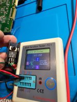
WWhatt...
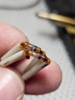
Why did they connect 2 thermistors here??? If it says R182 on the board below, the service manual says it's a resistor of 820 Ohms. On the working board of the right channel, there's also a thermistor here covered with some kind of rubber..
Why did they connect 2 thermistors here??? If it says R182 on the board below, the service manual says it's a resistor of 820 Ohms. On the working board of the right channel, there's also a thermistor here covered with some kind of rubber..
Attachments
That's a question for SE-A3 designers 🙂 The other two are in parallel as well. The PCB in the service manual doesn't correspond with what's inside the amp. Just follow the MK2 schematic and use 4x33k thermistors. I had the same board and mine were 33k.
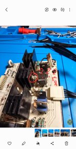
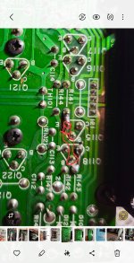
Heeere we gooo. I found the problem…
Oh man, how silly I was... There was a broken connection between two transistors that are linked together.
Until I decided to measure absolutely every single line between all of them… I would’ve never found it.
Phew… You can see in the picture where the break was.
Now I’m just happy I found the fault.
And video.. 🙂
Attachments

- Home
- Amplifiers
- Solid State
- Technics SE-A3 bias adjustment