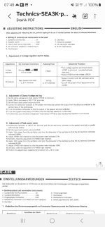
So how should I set it up to make it work optimally, as the factory recommends? The potentiometers ICQ and Clamp Voltage are a bit confusing... I don't have a distortion meter, but I do have an oscilloscope and a 200W dummy load.
With this amplifier, it seems that the idle current (bias) isn't adjustable??? Or am I mistaken, hmm.
It's not entirely clear to me what the clamp voltage is and how to set it... Ugh... I might have to go to a technician?
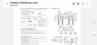
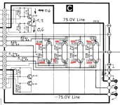
Here are two pictures from the service manual...
With this amplifier, it seems that the idle current (bias) isn't adjustable??? Or am I mistaken, hmm.
It's not entirely clear to me what the clamp voltage is and how to set it... Ugh... I might have to go to a technician?
Here are two pictures from the service manual...
Attachments
Icq is bias current adjustment. Without a distortion analyser you can not set it according to the service manual, all you can do is aim for the theoretical setting that was mentioned back in posts #7 and #8. You won't hear any difference even if you set it much lower, and lower is better for heat dissipation and reliability.
You will not see any distortion on a scope alone so I would just leave the other adjustment as it is, particularly if it has not been altered.
You will not see any distortion on a scope alone so I would just leave the other adjustment as it is, particularly if it has not been altered.
Unfortunately, the clamp voltage was adjusted—it was printed (marked). The boards were moving on the table while I was measuring, and the trimmers got shifted.
I'm also wondering if it's a good idea to replace the original trimmers with Bourns full trimmers? I have the same values at home as the ones listed in the service manual.
I'm also wondering if it's a good idea to replace the original trimmers with Bourns full trimmers? I have the same values at home as the ones listed in the service manual.
There was a broken connection between two transistors that are linked together.
I had the same problem with a pad lifted and cut from the trace. Sometimes you have to measure 10 times and find the problem on the 11th.
I replaced ALL the trimmers as I had 2 of the badly rusted, one with a broken leg.
For a start set the Iclamp at the middle and adjust Icq accordingly. You'll need to wait like 20 minutes for the current to settle. The inside part of the heatsinks will be warmer (less ventilation + PTs warming up) and you'll have different idle current readings there.
After how many millivolts should I set the bias after 20 minutes of idling?
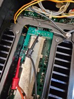
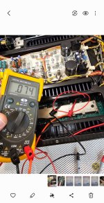
Currently, I have 100 millivolts on the left channel after 5 minutes and 61 millivolts on the right.
My trimmers look like new, visually.
I don't know to what value to set the bias for idle, as it's not stated anywhere in the manual.
Iclamp, kaj pomeni nastavitev na sredino? Fizično sredina trimerja ali glede upora?
am measuring the bias here. Is this correct?
Take a look at the picture
Attachments
Last edited:
"I have adjusted the PNP and NPN to 60
millivolts, approximately 30 millivolts per
transistor.
I managed to lower the left channel to 60
millivolts, but I couldn't do the same with
the right channel.
The trimmer reduces it to a maximum of 75
millivolts,
I'm not sure if these are the correct values
as specified by Technics
I read in a thread on page 7 that someone
adjusted it this way.
Could the trimmer be faulty, or is there
perhaps a resistor on this board, which was
previously operational, that is 'sleepy'? 🙂"
Attachments
Look at the schematic. It says 0.03 (30mV) per emitter which is 0.03mV/0.47Ohms=63.8mA per transistor. If you're measuring all emitters be careful not to make a short between transistors' pads or to heatsink.
Where exactly did you read that? I've been looking through the manual and I can't find it anywhere, or at least I don't see it.
Thanks
I just need to figure out why I can't reduce the bias on the left channel below 80 millivolts once the amplifier has been on for more than 30 minutes… meanwhile, the right channel still has some room on the trimmer to reduce it further.
On the left one, the trimmer is turned all the way.
Does iClamp also affect the bias?
No.Does iClamp also affect the bias?
Try increasing the value of the resistor that is in series with the bias preset.
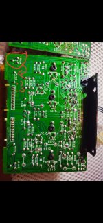
R138, the one I circled in post #29
(the circuits posted on this thread show different values, one shows 2.2k, the other 820 ohm)
(the circuits posted on this thread show different values, one shows 2.2k, the other 820 ohm)
Yes yes.. , well that’s the one I circled in the picture, the top post..
I’ll measure it to see if it really shows 2.2k ohms..
But what if the fault is in the sensor transistor? Those two small ones that are next to the main board near the possible transistors.
Q113, 114, 119 and Q120
I’ll measure it to see if it really shows 2.2k ohms..
But what if the fault is in the sensor transistor? Those two small ones that are next to the main board near the possible transistors.
Q113, 114, 119 and Q120
Yeah, that resistor isn’t suitable since it’s 1W and too powerful.
I need 2 fuse-type resistors, 120 ohms, 1/4W.
Does anyone have them at home by any chance?? I’m willing to buy...
I can’t find them anywhere...
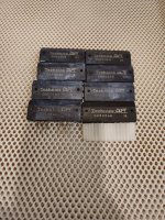
All the transistor packs need to be of the same rank (same gain and forward B/E voltage) per channel to ensure equal current sharing. If you fit mixed ranks you will find the bias current different for each pack.
Do your own risk assessment.
Fusible types were used in abundance years ago. They fail silently and without drama with the end user being unaware of a problem. A standard 1/4 watt may burn and may smoke under a fault condition. Assess the risks and fit accordingly.
Ask yourself whether the resistor is fusible to avoid scaring the customer if it fails, or is there a real fire hazard it it were to burn. If you are uncertain then you must fit the same as was removed.
I need 2 fuse-type resistors, 120 ohms, 1/4W.
Do your own risk assessment.
Fusible types were used in abundance years ago. They fail silently and without drama with the end user being unaware of a problem. A standard 1/4 watt may burn and may smoke under a fault condition. Assess the risks and fit accordingly.
Ask yourself whether the resistor is fusible to avoid scaring the customer if it fails, or is there a real fire hazard it it were to burn. If you are uncertain then you must fit the same as was removed.
- Home
- Amplifiers
- Solid State
- Technics SE-A3 bias adjustment