jneutron said:
I purchased 1 kilofoot of microphone cable out of parts express, as I had need for about 250 feet in a current application..and the price break made it very attractive to go with 1 kilofeet..
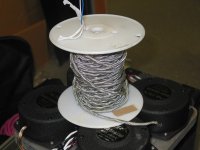
I just stripped the braid off a portion to make the double braid..it is copper braid, just tinned..
John
And this does come up with the CI of around 8 Ohms? Which type of mic cable, there seems to be so many kinds. I supplier gave me a samle that was only around 3mm in diameter. I'me sure that's not right. But don't mics have 3 conductors including ground?
janneman said:Sorry to quote my own post...
I found out that one Joule = one wattsecond. So, selecting a cable to minimize the CI (see post 27 figure) saves us say, 10 microjoules energy storage. That's 10^-5 wattseconds. Referred to an energy delivered by the amp to the speaker at 1 watt level for a second (1 wattsecond) a loss of 0.001% of energy by using the wrong CI. (We had already agreed that the other CI issue, reflections, was a non-issue).
Now, suppose the cable has a DC resistance of 0.08 ohms. That represents, for an 8 ohms load, a loss of 1%; a factor of 1000 higher than the mismatched CI. Why do we still need to take care of that CI? it seems a total non-issue if there ever was one. Can anybody enlighten me? I mean, this IS an engineering discussion.
Jan Didden
Hi Jan..
You must consider dissipative loss and stored-to-be-eventually-delivered signal independently. Dissipative loss is totally linear...more signal, more loss...so each channel sees same, (as far as I know). It's when a complex signal is introduced, that I would consider as the target issue..
Matched Z minimizes both L and C storage...and, both of those entities are lagging storage. At peak signal, the current is max, and so is voltage..
The entire premise of wires making a difference hinges entirely on what is audible...my point to date is, audibility of localization is hugely more sensitive to interchannel anomolies in amplitude; .06dB for one foot of shift at one specific 2 D location, and 5 to 10 uSec ITD's for the same effect.
Localization research is at present, in it's infancy..the best researchers I've discussed this with have nothing along these lines..the best I've seen so far has been comparison of ITD of one signal with IID of another non-correlating one...I've found no research which tests our limits with ITD/IID correlated and compared in virtual space, with another separate source with it's own ITD/IID correlated signals... ....which of course, is exactly what we do to localize sounds...without thinking, how difficult is it for us to determine the location of two different tone bells when they are a foot apart and ten feet away...(eyes closed, which bell is on the right...the higher pitch, or the lower one???)
Why is it we build and engineer binaural reproduction systems, without actually modelling what it is we are trying to do with the system😕 😕 😕
Not having found any research along these lines, I must conclude that I am breaking new ground...it is of course, possible, that I need develop better literature research skills, but so far, I've come up blank..kinda like my developing a design for a 75 ohm RCA plug and jack, and finding someone patented it 31 days earlier...oh well..
Cheers, John
SY said:
When you can find speakers matched to that level, let me know!
I wouldn't worry about the absolute matching, I'd worry about shift. We can't keep our head steady enough to worry about absolute..
John
jneutron said:
Why is it we build and engineer binaural reproduction systems, without actually modelling what it is we are trying to do with the system😕 😕 😕
Not having found any research along these lines, I must conclude that I am breaking new ground...it is of course, possible, that I need develop better literature research skills, but so far, I've come up blank..
Cheers, John
I have an article out of Wireless World that talks about binaural reproduction and tries to come up with a circuit that is to compensate for speaker location. But I think really this effort needs to jointly be handled with the recording inductry in order to make sense. If you don't record right taken into consideration IID and ITD, and do mixing right, there is really not much the playback system can do.
soongsc said:And this does come up with the CI of around 8 Ohms? Which type of mic cable, there seems to be so many kinds. I supplier gave me a samle that was only around 3mm in diameter. I'me sure that's not right. But don't mics have 3 conductors including ground?
I forgot what kind, but PE had it at reasonable cost per foot, 170 bucks for the spool.
I stripped the cable and took the wire pair out...anyone need some blue/white #22 twisted pair??😀 😀
Pic attached of the braid off the cable, spooled over the guts of the wire..
Oh, the 8 ohms (about) comes from the dielectric (tefzel, at DC=2.7) heatshrunk over the inner braid, final thickness of about 10 thousandth of an inch..This insulation DC, thickness, and diameter strictly define the Zline.
For my next cable, I need to work with insulation in the 20 to 40 mil thick range (physical limitations on manufacturing processes for the dielectric which I chose that has DC=1.05), this defines the OD of the inner braid..(I got a spreadsheet for that as well 😀 😀 😀 ...I gots one for everytin...)
Cheers, John
Attachments
soongsc said:I have an article out of Wireless World that talks about binaural reproduction and tries to come up with a circuit that is to compensate for speaker location. But I think really this effort needs to jointly be handled with the recording inductry in order to make sense. If you don't record right taken into consideration IID and ITD, and do mixing right, there is really not much the playback system can do.
Miking techniques are a very big part of it..
The recording studio apps for my research will be: during mixdown, location assignment has to be a combination of amplitude setting, much in the way a pan pot works, as well as time delay setting..both together are needed to provide correct placement of the image. Using one is very artificial, while we can image based on IID, for example, it is not a correct one.
The actual numbers are dependent on speaker placement..distance and angle from the listener...so unless some exact reproduction format is established, all one can do is approximate. Different speaker arrangements, as well as type (point, line, or planar) will affect ITD and IID, so some compromise would be required..
Cheers, John
Kuei Yang Wang said:Konnichiwa,[snip]Any alteration induced by resistance are strictly linear, any induced by energy storage are not really linear, certainly not with transient signals.
Sayonara
Thorsten,
Why not? The L and C are linear, aren't they?
Jan Didden
jneutron said:[snip]Matched Z minimizes both L and C storage...and, both of those entities are lagging storage. At peak signal, the current is max, and so is voltage..[snip]Cheers, John
John,
As I asked Thorsten, this is not clear to me. We have lots of L and C in signal chains, filters, crossovers etc, and the effects are totally understood in terms of phase shift, attenuation and/or delay. These effects donot subtract from the sound quality as such. Why is it that the L and C of a cable (which can satisfactorily be lumped to a single value at the freq range of interest) now are presented as some special case that DOES decrease the sound quality?
Jan Didden
PS John I appreciate your concerns with localisation etc, and I understand the importance. But since this is a thread about speaker cables (and because I, admittedly, don't know diddly about localisation) so I keep asking these questions on cables. ....
janneman said:Why not? The L and C are linear, aren't they?
Jan Didden
Hi Jan, figured I'd chip in...
My understanding is that the inductance will be, umm, interesting...I don't know what to call skin effect based frequency dependent inductance..is it linear, non linear, or piecewise linear??...and, I've found no rigorous mathematical solutions to this question for reasonable wires in the audio band at audio impedances...I can't claim it is audible, or not...I just don't know the mathematical analysis..that is why I'm workin on my mag analysis code, to include current slew stuff..
Capacitance, well, everybody talks about how "dielectric involvement" aka capacitors, is audible with speaker wires...I find no support for that...nothing credible anyway...
Cheers, John
janneman said:
John,
As I asked Thorsten, this is not clear to me. We have lots of L and C in signal chains, filters, crossovers etc, and the effects are totally understood in terms of phase shift, attenuation and/or delay. These effects donot subtract from the sound quality as such. Why is it that the L and C of a cable (which can satisfactorily be lumped to a single value at the freq range of interest) now are presented as some special case that DOES decrease the sound quality?
Jan Didden
As far as I can tell, I've found nobody who knows how to measure low impedance fast signals accurately..
My previous work experience involved measuring 8 kiloamperes per microsecond signals into a one ohm load..I learned to appreciate what is involved in getting fidelity of measurement down pat. My present job required measuring 6 Kiloamperes at 60 hz across a 250 uOhm shunt to within about 5 millivolts, requiring re-engineering the tap pickups to drop the error voltage down from 1.3 volts..I was measuring the temp rise on a 3 inch diameter diode by looking at the V/I curve up and down the current waveform, the curve hysteresis represents the instantaneous temperature.
janneman said:PS John I appreciate your concerns with localisation etc, and I understand the importance. But since this is a thread about speaker cables (and because I, admittedly, don't know diddly about localisation) so I keep asking these questions on cables. ....
Hmmm. so, I'm about a half a step ahead of ya??😉
Without actually considering what we are trying to do with the binaural system, all that would be left is...R,L, and C...setting specs on that for speaker cables just starts the old can hear/can't hear arguments all over again..
I take a different tact...what exactly do we hear??..
Cheers, John
jneutron said:
As far as I can tell, I've found nobody who knows how to measure low impedance fast signals accurately..
My previous work experience involved measuring 8 kiloamperes per microsecond signals into a one ohm load..I learned to appreciate what is involved in getting fidelity of measurement down pat. My present job required measuring 6 Kiloamperes at 60 hz across a 250 uOhm shunt to within about 5 millivolts, requiring re-engineering the tap pickups to drop the error voltage down from 1.3 volts..I was measuring the temp rise on a 3 inch diameter diode by looking at the V/I curve up and down the current waveform, the curve hysteresis represents the instantaneous temperature.[snip]
... which is quite interesting, but doesn't address my question at all, but that's OK. I'm used to questions being ignored if they are hard enough

jneutron said:[snip]Hmmm. so, I'm about a half a step ahead of ya??😉
[snip]Cheers, John
+/- 2dB, yes😉
Jan Didden
janneman said:... which is quite interesting, but doesn't address my question at all, but that's OK. I'm used to questions being ignored if they are hard enough
Jan Didden
OOOOOOHHHH...goood one...

Ya know??? your right, I didn't answer the question very well...
Within the signal chain, the high impedance runs do not have significant energy storage in terms of inductance via current.. if you calc'd the total storage of .2 uH for a 10 Kohm run, the inductive component is trivially small.
It's when you try to measure the current in low impedance circuits that the inductance can really start to affect the measurements..the measured voltage really starts to lag the current, and takes on incorrect numbers.. And, since inductance is actually a measure of the external magnetic field around a wire, it also gives insight into loop pickup..
Bottom line, I see lots of inherent errors in understanding when it comes to low impedance design..not the active circuitry mind you, but how the stuff is put into a case, and how the end result, speaker current, is measured...lotsa slop in the methods..
High impedence, on the other hand...is cake...
Cheers, John
Konnichiwa,
Not in the transient sense.
The problem with this whole discussion and much more in audio is the relentless search fo oversimplification and overabstraction beyond usefullness and the desire for single number "figures of merit".
Witness THD, IMD, DF, Frequency Response Flatness and many other such one dimensional measures which are notable only for the extreme and amazing consistency by which they invariably fail to give any numerical qualification od "good sound".
Attempting to view the cable in isolation from it's application invariably places you well boundary where your abstraction can still yield usefull results.
Unless you consider the entire system, including the desired signal, system internal generated undesired signals (in other words distortion/noise/interference) and system external generated undesirable signals (RFI, EMI et al) and their ability to intermodulate, crossmudulate and otherwise intermingle with the desired signal you cannot get to any useful conclusion.
That is why in may ways the basic premise of this thread at the very start is invalid.
We can further argue about measuring that which extends past the oversimplifed and stand alone RLC view of the cable, but that isa complex story.
Sayonara
janneman said:Why not? The L and C are linear, aren't they?
Not in the transient sense.
The problem with this whole discussion and much more in audio is the relentless search fo oversimplification and overabstraction beyond usefullness and the desire for single number "figures of merit".
Witness THD, IMD, DF, Frequency Response Flatness and many other such one dimensional measures which are notable only for the extreme and amazing consistency by which they invariably fail to give any numerical qualification od "good sound".
Attempting to view the cable in isolation from it's application invariably places you well boundary where your abstraction can still yield usefull results.
Unless you consider the entire system, including the desired signal, system internal generated undesired signals (in other words distortion/noise/interference) and system external generated undesirable signals (RFI, EMI et al) and their ability to intermodulate, crossmudulate and otherwise intermingle with the desired signal you cannot get to any useful conclusion.
That is why in may ways the basic premise of this thread at the very start is invalid.
We can further argue about measuring that which extends past the oversimplifed and stand alone RLC view of the cable, but that isa complex story.
Sayonara
jneutron said:
Hi Jan, figured I'd chip in...
My understanding is that the inductance will be, umm, interesting...I don't know what to call skin effect based frequency dependent inductance..is it linear, non linear, or piecewise linear
Cheers, John
You're starting to sneak that "skin effect" term in there again. 😉
soongsc said:If someone could come up with a software that could scan in a room interior, allow the user to point to where the performers will be, and then allow computerized calculation of optimum mic locationing, then this might be a big revolution in the recording industry.
The big problem with it that the ideal recording method ( puting a mic(array) to the best seat of the house ) that it is not compatible with the stereo playback.
fcserei said:
The big problem with it that the ideal recording method ( puting a mic(array) to the best seat of the house ) that it is not compatible with the stereo playback.
Of course you want additional processing to make it compatible with stereo, 5.1 or 7.1. Most recordings use multi-mic recording anyway. Rather, there would be lots of processing options because your exact performer locations are known, the mic locations are known, you could really post impose performers more accurately.
However, this is not the main subject of the thread. Sounds like a new thread is necessary?
Kuei Yang Wang said:Konnichiwa,
Not in the transient sense.
[snipped discussion on system issues]
Thats it? I ask about linearity (or not) of L and C, and this is the answer? This should convince me that they aren't linear?
Jan Didden
jneutron said:
Hi Jan, figured I'd chip in...
My understanding is that the inductance will be, umm, interesting...I don't know what to call skin effect based frequency dependent inductance..is it linear, non linear, or piecewise linear?? [snip]Cheers, John
So? I measure x uH at 20Hz and x+20% uH at 20kHz. So what? I lose 0.1dB extra at 20kHz re: 20Hz. So what?
Jan Didden
janneman said:
So? I measure x uH at 20Hz and x+20% uH at 20kHz. So what? I lose 0.1dB extra at 20kHz re: 20Hz. So what?
Jan Didden
Gee Jan, you really oughta get your facts straight before you post..(my turn)
When current density re-distribution occurs, (the entity formerly referred to as "skin effect"), two things happen..
1. The current moves to the outside of the conductor.
2. The inductance of the wire drops...at the limit, 15 nH per foot drop.
Not rises as in your example....sheesh....😉
You make the statement "so what", like you are confident that .1dB is not audible..upon what would you base that in reference to soundstage reproduction??
For what has been bandied about as "audible", yes you are absolutely correct with respect to monophonic reproduction. But for localization stability, it may be too loose. Recall as a first pass, .06 dB variation causes image uncertainty of about a foot, ten feet away...
To keep storage energy minimal, the line Z should be, say, 8 ohms? My cable ran 10 nH per foot, 288 pf per foot, line Z of 5.89 ohms..if I used a solid inner conductor, the line Z?? 15 nH Plus 10....25 nH per foot, line Z = 9.31 ohms..
At DC, line Z is 9.31, at hf, 5.89....the L vs freq curve at 8 ohm load???who knows, currently an intractible math problem..
You ask very relevant question, Jan....but statements such as .1dB (so what) are indicative that you (as you stated up front) do not understand the ramifications of localization and soundstage simulation...you are in good company as many of the researchers I discuss this with are also unhindered with experience along this avenue of thinking..
This is ok, in fact, it is very good...you ask reasonable questions that require accurate answers...I appreciate that..
Cheers, John
jneutron said:
When current density re-distribution occurs, (the entity formerly referred to as "skin effect"), two things happen..
1. The current moves to the outside of the conductor.
2. The inductance of the wire drops...at the limit, 15 nH per foot drop.
Cheers, John
Gee John!
In the beginning I thought you did not agree "skin effect" exists. Now I'm getting the feeling that you agree that there is skin effect, but the other sources did not explain it in the correct manner. It this understanding correct?
- Status
- Not open for further replies.
- Home
- General Interest
- Everything Else
- Technical discussion on loudspeaker cable