Reply to Original Posted Question
I paraphrase here what was orignally asked by the person who started this thread:
1. "How are the R, L, C, Z, skin or cross coupling large enough at audio frequencies to matter"?
I am now going to provide some short answers, which I will elaborate on later.
A1:
L has the potential to cause a direct roll-off of FR in the audio band due to the sheer amount of L interacting with certain low impedance loads, such as electrostatic speakers, difficult system loads such as a Wilson WAMM, etc.
A2:
R causes FR variations due to the varying impedance of the speaker system.
A3:
C causes amp instability for amps that are not unconditionally stable under all possible loading conditions.
A4:
Z issues are traditionally dismissed if the cable length is less than 1/2 to 1/4 the electrical wavelength of a signal within the cable.
This has to do more with whether or not lumped or distributed cable parameters are counted as relevant.
However, there are other issues that do not depend on this, such as how much the cable might act as an antenna, how the cable might influence the amplifier feedback network if there are multiple signal reflections back and forth because the cable is not 'terminated'.
A5:
Skin/Self Inductance can be big enough on very large single conductors (approx. 18 ga. and up) to cause a difference in current density between the center and the surface of a conductor.
A6:
I am not sure exactly what you mean by cross-coupling, so perhaps it would be best if you explained what this was first.
2. "How can cable C loading be an issue when there are 10's of uF in the speaker crossover?
Corollary: How can R matter, or L, if the speaker VC has XX amount of R and ZZ amount of L?
B1:
The speaker crossover capacitance is a part of a total filter circuit, and is not in direct shunt with the speaker cable or the speaker system input, but rather, is in series with a tweeter, or is a HF shunt for a woofer, etc. AFTER being isolated by an inductor. The capacitance within the crossover has been factored into, and become a portion of the total loudspeaker system transfer function, and can be treated in a "Black Box" manner, that is, it is not normally taken into consideration.
B2:
By the same token, the driver voice coil resistance and inductance are a part and parcel of the speaker driver itself, and are not normally considered a seperate aspect away from the speaker unit itself.
In point of fact, the voice coil is a portion of the speaker motor system, and is immersed within a magnetic field. As such, it is an active part of the driver, and not a passive one. It's R and L are not normally a consideration outside the speaker box, unless they are abnormal in some way.
MORE DETAILED REPLIES:
I am going to preface these with an observation that has relevance to a more detailed discussion of cable effects.
Many people seem to think that we only need to be concerned with signal distortions that are fairly large, that is, distortions that are larger than 1% or 0.5% (or some other arbitrary level, based on whatever favorite theory). Most of these kinds of thought processes seem to be based on trying to correlate what we may hear, with what has been researched in an acoustics lab, or in a psycho-acoustics study. These kinds of metrics often include, JND's for various distortions, such as THD, IM, etc., however, the fact is, no real correlation has ever been established between these kinds of studies, and what we hear when we listen to music during a home playback event.
Thus, we can not say that because we can only hear down to (an example only, not necessarily a correct amount/level) say, 0.5% 3rd harmonic distortion at 200 Hz, that if an audio component has less than 0.5% distortion, it is audibly perfect. Aside from all of the variables involved, such as our ability to hear different levels of distortion at different frequencies, etc., the psycho-acoustic studies performed can not be translated over to what can be heard with music and modern playback systems.
One point many are not aware of is that many of these studies used what are called "Lab Grade Speakers", which is a long (deep) rectangular box enclosure that contains an 8" whizzer cone fullrange driver equalized to be "flat" in FR. They were made and sold by Neutrik, B&K and other such companies. The thing is, if you ever heard music through one of these, you would run screaming from the room in horror, they are abysmal in terms of being able to replicate music. Yet these were what were often used for such psycho-acoustic studies, used to determine JND's, etc.
Has any of you ever heard a Thiel CS7 or 7.2?
This is an extremely low distortion loudspeaker when operated at moderate to low levels, and it's playback purity is so startlingly clean and pristine, that is is a shock to hear it under good system conditions. I have no doubt that if such a speaker system were used to determine various JND's, that the levels would be found to be at a lower level than before.
Yet this still belabors the point. We can't take these simple one dimensional numbers and apply them to a multidimensional signal such as music. My point is that we can hear much lower down in distortion that many tend to believe.
The reason for my belief is that we can readily hear what different digital audio dither algorithms sound like. UV22 vs. Super Bit Mapping, vs. PowRbit, etc., these all sound quite different in nature, and not just at low signal levels, but all across the range and tone.
Yet these signal manipulations are all occuring at levels BELOW -90 dB, and would (if translated into single dimension metrics) be equivalent to distortion of only 0.003% or less.
Thus I feel that we can not dismiss signal distortions, just because they may be below some arbitrary level that someone else has decided is "too low to hear", without any actual evidence or data to base this opinion on.
In this thread so far, levels of 0.5% have been mentioned, which is -46 dB.
As I have noted, it is entirely possible that we should be considering signal abberations that are as low as -90 dB down, in order to be sure we include all the factors that might be heard, rathetr than deciding arbitrarily that they can not be heard.
RE A1:
With difficult speaker loads that go below 4 ohms in the HF's, it is entirely possible to have a speaker cable that actually rolls off the response within the audio band due to cable inductance. Contrary to popular claims, this does not tend to occur primarily with "fancy" speaker cables, but is one of the many flaws that plague zip cord type speaker cables.
Since this is the kind of thing that tends to make cable naysayers very nervous and upset, it is the one aspect that gets the most denial and the most attempts made to ignore this inconvenient little fact.
The high performance speaker cables use various different geometries to try and minimize cable inductance, using braided multiple wires, thin flat ribbons, coaxial construction, etc., but often ending up with a very high capacitance instead. That aspect will be covered later.
RE A2:
It takes an amazingly small amount of cable resistance to create a variation in the frequency response of a speaker system, due to the varying nature of the speaker system's input impedance.
One of the criteria used by objectivist's who favor ABX style DBT testing, is that the frequency response should not vary more than 0.1 dB, or a simple FR variation could be responsible for "hearing a difference". Thus, if one wants to avoid using their speaker cables as a "tone control", or in other words, avoiding signficant FR variations due to speaker cable resistance, then the speaker cable must have a total net AC resistance no greater than 1/100th that of the LOWEST impedance of the speaker system across the audio band.
That would then include any inductive rise due to a high inductance speaker cable, and keep the FR deviation due to loudspeaker system input impedances and loudspeaker cable resistance below 0.1 dB
With many loudspeaker systems that are nominally 8 ohms, they may dip down to 5 or 6 ohms, meaning that in order to avoid a FR variation greater than 0.1 dB, the speaker cable TOTAL ROUND TRIP RESISTANCE must be less than 0.05 ohms.
This equates to the following lengths, and the required gauge to keep below 0.05 ohms:
10 foot run - 16 ga.
20 foot run - 14 ga.
30 foot run - 12 ga.
This is one of the reasons that many folks who are not concerned about high performance cables otherwise will recommend using 12 ga. zip cord, it will tend to minimize the simple voltage divider FR errors due to the loudspeaker's input impedance varying.
Ref:
Meyer, E. Brad.; "The Amp/Speaker Interface", Stereo Review, vol. 56, pp. 53-56 (1991, June)
Continue to Part 2
Jon Risch
Reply to Original Posted Questions, Part 2
Part 2
RE A3:
In designing for a low inductance, many high performance cables end up with a somewhat high capacitance, as the very same techniques that serves to lower the inductance, tends to increase the capacitance.
Will this increased capacitance cause a HF roll-off? Not with the vast majority of power amps. If you sit down and do the math, even a tube amp with 1 ohm of output impedance will not cause a HF roll-off due to cable capacitance.
However, relatively large amounts of speaker cable capacitance, in conjunction with the lowered inductance, can cause some less than unconditionaly stable power amps to break into oscillation, and distort, overheat, blow fuses, damage transistors, etc.
Technically, this is a power amp problem and issue, the amp is at fault, not the cable. However, only NASA and the Military can demand wholly unconditionally stable power amps, and afford to pay for them. Most home hifi playback power amps (or receivers, integrateds, etc.) will break into oscillation at SOME value of load capacitance, it is just a matter of how much will it take.
If we look at the typical values of C for the more problematic speaker cables, it tends to run in the 400-700 pF per foot range, and with cable lengths of 12 to 25 feet not that uncommon, we see a range of capacitance from about 4800 pF to 17,500 pF (or 0.018 uF). It is this range of capacitance that is most likely to set off an unstable amp.
In some cases, once you get above 0.02 uF, the amp will stop oscillating continuously, at least until you reach another level of several uF's of capacitance. Other amps may not start oscillating until the capacitance reaches 0.01 uF and above. Others are know for their lack of stability, such as the older Naim power amps, which often would oscillate even when used with simple zip cord of lengths longer than 15-20 feet. This represents a capacitance as small as 300 pF.
Obviously, we don't want the amp to oscillate, or behave unstably, so it is best to avoid cables with the dangerous levels of capacitance presented to the amp. Note that an amp that would have a problem with 25 feet of a 500pF per foot cable, might be perfectly happy with a length of that same cable that was only 6 feet long, so the total capacitive load is what matters.
For most amps that have problems with a highly capacitive speaker cable, use of an RC network (often referred to as a Zobel) placed at the speaker end of the cable, can help improve stability enough to prevent outright problems.
Ref:
http://sound.westhost.com/cable-z.htm
RE A4:
Cable Z has an influence on several things that are not limited to whether we look at lumped or distributed parameters as relevant.
The characteristic impedance of a speaker cable can influence how much the cable will act as an antenna, with a cable with a very high characteristic Z being more prone to RFI pickup than one with a lower characteristic Z.
BTW, it might help to throw out some values for typical speaker cables, most tend to run on the high side compared to the speaker input Z.
Zip cords range around 100-200 ohms, and many of the high performance cables are somewhere below that, down to 40-50 ohms, while some even approach a similar Z as the speaker load, or close to 8 ohms.
Aside from RFI pickup, what other aspects will the cable impedance affect? Amp stability is also affected by the cable characteristic Z.
Ref:
http://sound.westhost.com/cable-z.htm
Then there is the issue of how any signal that is attempting to enter into the amp outputs will also be connected to the feedback loop of the amp. Often there is little isolation from the amp output to the feedback loop node, as the feedback is taken right from the amp's output, with perhaps a simple LR circuit in series with the actual speaker terminals. Some amps have a true Zobel network at the amp output, to help terminate the amp at RF, and reduce susceptibility to RF region loading or lack thereof.
Much is made of the fact that transmission line issues are not anything to be worried about at audio frequencies, but what about reflections that could occur when a speaker cable is not terminated by it's characterisitc impedance? On a transient signal, it may be possible for this impedance mismatch to allow a reflected signal to bounce back down the cable to the amp after reflecting off of the speaker load. Given that the power amp is also NOT a good termination or a source matched driving situation, the signal could reflect back down the speaker cbale and again off of the speaker load.
Now, instead of having one single reflection, we may have a series of them. So what you may ask? This could be injected into the feedback loop, and cause the amp to attempt to "correct the error", and send a series of pulses through the amp circuit.
Inevitably, someone will mention that the level of these misterminated relfections will be very low, and thus, not of any concern. But keeping in mind what I said earlier, that signal abberations as low as -90 dB might be an issue, perhpas we should not be so quick to dismiss such things. In addition, this kind of signal distortion would not be harmonically related, it would be a time domain distortion, and oe that lingered on in time.
Those familair with amplifier design will know what some of the potential problems and issues are, and why they probably can not be ignored.
Ref:
Deletraz, Herve: "Reflections, Echos & Music", Stereophile magazine, Nov. 2001, p. 59 -
RE A5:
Some people lke to claim that skin effect can not possibly impact on the audio band, that it is an RF only kind of issue.
Yet the fact remains that for wires larger than approx. 18 ga., the AC resistance is different for 20 Hz than it is for 20 kHz.
Is this difference enough to directly/significantly impact the frequency response? No, and this is where most people stop. However, the mere fact that there is a change in the current distribution from LF's to HF's means that other less obvious aspects can arise, not just simple amplitude, but other more subtle aspects. Skin effect may be one of the driving forces behind what has been called strand jumping.
If strand jumping ocurs, and both skin effect and self-inductance are possible driving forces, then for the larger diameter conductors, solid wires should have a sonic advantage over stranded ones.
Is this an issue with coaxial braids? Probably not, as the size of the braid layer is not that large, and there are usually only two wires crossing over one another, rather than a large bundle several wires deep. Is it an issue with 12 gauge wires? Probably, as this is such a large diamter, that even with consideration of a modified sert of skin effect equations (Bessel), etc, the sheer diamter is just so large, that by 20 kHz, there is a significant difference in current density between the center and the outer surface.
RE B1:
I don't think that I need to belabor this one, the difference between a shunt capacitance that is across the main full trange signal, and a series cap in a crossover circuit for a tweeter, or a shunt cap after an inductor for a woofer are not at al the same thing, and do not have the same filter effects on the signal.
The crossover components are intended to filter and shape the response, the cable shunt capacitance will not directly affect the measured FR to a signficant degree, but it WILL be a factor in whether or not the amp remains stable!
RE B2:
The voice coil resistance and inductance are a part and parcel of the loudspeaker, and are intimately involved with the active workings of the loudspeaker, and as such, are not in the same class as a resistance or inductance parameter for a passive device like a cable. The cable is out there all alone and by itself, at the mercy of the source Z and the load Z, including any reactive components present, and the cable L, C, and R will interact in a complex manner with the total system circuit.
These are just a partial answer to the original posted questions, and do not go into full detail or depth, but should suffice for the time being. There are other cable parameters that may be in play as well, that were not mentioned by the original poster, and I will discuss those in a furture post.
I will also attempt to address the many posts by jneutron regarding his theories on localization at some point, as time permits.
Jon Risch
I fully agree with what Jon explained. There is one thing that I can't quite understand.
So now it seems the limiting factor would be amplifier stability once you get optimum speaker cables because capacitance has to increase to keep Z low? How would capacitance effect fully digital amplifiers that use PCM type signals?
So now it seems the limiting factor would be amplifier stability once you get optimum speaker cables because capacitance has to increase to keep Z low? How would capacitance effect fully digital amplifiers that use PCM type signals?
Konnichiwa,
A fully digital amplifier using PCM (which really means multibit) would in fact be an analoge amplifier by all accounts. If it operates open loop it would care FA about what you hang off the back, if it involves looped feedback you have the same issues.
I think you are refering to a switched amplifier (Class D,T,DSD et al) which is bitstream. Again, the answer depends strictly on the operation mode. if there is no analogue domain looped feedback it should matter FA what you hang off the back, however such amplifiers invariably require a lowpass of a reasonably high order after the amplifier to get rid of switching noise and high capacitance may very well "detune" this filter sufficiently.
As with all issues involving cables, we need to consider the entire system including secondary and tertiary parasitic effects if we wish to understand the issues involved.
Sayonara
soongsc said:How would capacitance effect fully digital amplifiers that use PCM type signals?
A fully digital amplifier using PCM (which really means multibit) would in fact be an analoge amplifier by all accounts. If it operates open loop it would care FA about what you hang off the back, if it involves looped feedback you have the same issues.
I think you are refering to a switched amplifier (Class D,T,DSD et al) which is bitstream. Again, the answer depends strictly on the operation mode. if there is no analogue domain looped feedback it should matter FA what you hang off the back, however such amplifiers invariably require a lowpass of a reasonably high order after the amplifier to get rid of switching noise and high capacitance may very well "detune" this filter sufficiently.
As with all issues involving cables, we need to consider the entire system including secondary and tertiary parasitic effects if we wish to understand the issues involved.
Sayonara
I'm actually referring to Pulse Width Modulation type driving signals. Sorry for the missuse of terminology. Normally these do not have feedback. Such as TACT. There are also some digital chip amps of smaller power out there.
Re: Reply to Original Posted Question
Welcome the the fray, Jon..
The R within the magnetic field is considered a passive element within the motor structure, and certainly needs to be considered. L within strictly defines the energy stored by the voice coil, which also considers the field that is enhanced and stored by the motor structure, so it is significantly more complex in nature..
http://www.audioasylum.com/forums/prophead/messages/11938.html
I meant a two dimensional FFT, of the same type as is used for vision recognition systems..one which has as the plot variables, x and y in space, with the integrated volume under the surface indicative of virtual image sharpness.
So far, for image stability to a foot level, 5 uSec coherence and .06 dB coherence..at any signal level.. coherence being the key, hense the two dimensional FFT analysis..
Cheers, John
Welcome the the fray, Jon..
Z, L, and C are intimately locked together. What has traditionally been dismissed has been based on wavelength, which is an incorrect argument..L and C are dependent on Z.Jon Risch said:Z issues are traditionally dismissed if the cable length is less than 1/2 to 1/4 the electrical wavelength of a signal within the cable. This has to do more with whether or not lumped or distributed cable parameters are counted as relevant.
The maximum inductive change is exactly 15 nH per conductor per foot..using the correct equations for skin depth results in much smaller R variation than the TEM depth penetration equations would have us believe. The question is, can that inductance change be heard...Jon Risch said:Skin/Self Inductance can be big enough on very large single conductors (approx. 18 ga. and up) to cause a difference in current density between the center and the surface of a conductor.
Jon Risch said:By the same token, the driver voice coil resistance and inductance are a part and parcel of the speaker driver itself, and are not normally considered a seperate aspect away from the speaker unit itself.
In point of fact, the voice coil is a portion of the speaker motor system, and is immersed within a magnetic field. As such, it is an active part of the driver, and not a passive one. It's R and L are not normally a consideration outside the speaker box, unless they are abnormal in some way. .
The R within the magnetic field is considered a passive element within the motor structure, and certainly needs to be considered. L within strictly defines the energy stored by the voice coil, which also considers the field that is enhanced and stored by the motor structure, so it is significantly more complex in nature..
Perhaps yes, perhaps no..but certainly an interesting topic of research..Jon Risch said:Many people seem to think that we only need to be concerned with signal distortions that are fairly large, that is, distortions that are larger than 1% or 0.5% ...... ....... I have no doubt that if such a speaker system were used to determine various JND's, that the levels would be found to be at a lower level than before..
Hmmm...when I posted the statement "two dimensional problem at prophead two days ago, I meant literally, not figuratively..you apparently did not understand the term as I intended.Jon Risch said:We can't take these simple one dimensional numbers and apply them to a multidimensional signal such as music...
http://www.audioasylum.com/forums/prophead/messages/11938.html
I meant a two dimensional FFT, of the same type as is used for vision recognition systems..one which has as the plot variables, x and y in space, with the integrated volume under the surface indicative of virtual image sharpness.
My point is actually along the same lines..but I include ITD and IID as "distortion", that distortion being in two dimensions, not one as all the JND studies have tested.Jon Risch said:My point is that we can hear much lower down in distortion that many tend to believe....
Jon Risch said:Yet these signal manipulations are all occuring at levels BELOW -90 dB, and would (if translated into single dimension metrics) be equivalent to distortion of only 0.003% or less. ....
So far, for image stability to a foot level, 5 uSec coherence and .06 dB coherence..at any signal level.. coherence being the key, hense the two dimensional FFT analysis..
I believe you are limiting yourself by trying to apply the incorrect measurement tool..FFT analysis is not even capable of spotting ITD, and signal subtraction is very difficult when one of the signals is low impedance...wrong tool there..Jon Risch said:As I have noted, it is entirely possible that we should be considering signal abberations that are as low as -90 dB down, in order to be sure we include all the factors that might be heard, rathetr than deciding arbitrarily that they can not be heard.....
Tsk tsk..you were doing well up to this point..I recommend you leave this garbage on the cutting room floor, it does not belong here..it is a tactic used by those who have nothing of substance to say..Jon Risch said:Since this is the kind of thing that tends to make cable naysayers very nervous and upset, it is the one aspect that gets the most denial and the most attempts made to ignore this inconvenient little fact. .
Based on IID/ITD equations so far, I'm talking about .06 dB level variations as being audible at the one foot image stability level..small enough for whatcha talkin bout??😉Jon Risch said:It takes an amazingly small amount of cable resistance to create a variation in the frequency response of a speaker system, due to the varying nature of the speaker system's input impedance..
Try about half that, interchannel, for a one FOOT blurring of the image..Jon Risch said:One of the criteria used by objectivist's who favor ABX style DBT testing, is that the frequency response should not vary more than 0.1 dB, or a simple FR variation could be responsible for "hearing a difference". Thus, if one wants to avoid using their speaker cables as a "tone control", or in other words, avoiding signficant FR variations due to speaker cable resistance, then the speaker cable must have a total net AC resistance no greater than 1/100th that of the LOWEST impedance of the speaker system across the audio band. That would then include any inductive rise due to a high inductance speaker cable, and keep the FR deviation due to loudspeaker system input impedances and loudspeaker cable resistance below 0.1 dB..
Good info if we are worried about .1dB..not so clear how it affects interchannel coherence, though, at the .06 dB level.Jon Risch said:With many loudspeaker systems that are nominally 8 ohms, they may dip down to 5 or 6 ohms, meaning that in order to avoid a FR variation greater than 0.1 dB, the speaker cable TOTAL ROUND TRIP RESISTANCE must be less than 0.05 ohms.
This equates to the following lengths, and the required gauge to keep below 0.05 ohms:
10 foot run - 16 ga.
20 foot run - 14 ga.
30 foot run - 12 ga.
..
Cheers, John
Re: Re: Reply to Original Posted Question
I think you either need to change the "one foot" to either "arc-minutes" or arc-degrees", or add distance to that to make the measurement precise. How far way is that "one foot difference" anyway?
jneutron said:Welcome the the fray, Jon..
Based on IID/ITD equations so far, I'm talking about .06 dB level variations as being audible at the one foot image stability level..small enough for whatcha talkin bout??😉
Cheers, John
I think you either need to change the "one foot" to either "arc-minutes" or arc-degrees", or add distance to that to make the measurement precise. How far way is that "one foot difference" anyway?
Re: Reply to Original Posted Questions, Part 2
How much the cable acts like an antenna will depend heavily on the geometry, where the distributed L and C are, as well as the standard braid coverage and skin depth vs high frequency characteristics. But the statement that pickup is directly related to Z is not correct..for a zip, certainly, as well as some other styles.
 ..thank you.
The driving force is the reaction of the wire's conductivity to the rate of change of the magnetic field within the conductor..One can use either faraday's law of induction, or Lenz's law of exclusion..
Stranded affects the conductivity internally..
Strand jumping is NOT what happens to the primary driving signal. It refers to the direction of the current loops which are normal to the current flow and normal to the internal magnetic fields.."strand jumping" is an entirely orthogonal component of the eddy currents..if the conductors have a bad connection, there is no "strand jumping"..and the magnetic field penetrates (actually, is excluded LESS) further into the conductor.
Not much, the actual bessels for 20K and #12 run about 73 percent current level at the center of the wire, whereas the INCORRECT exponential equations predict 20% density..clearly, a huge discrepancy...this is why the exponential APPROXIMATION is so inaccurate.
Actually, every single thing I have said is not just theory, but actuality..aspects of my localization are part of radar theory, GPS theory, sonar, ultrasonic ranging and localization, cell phone theory, and computer based image recognition..all tried and true technologies applied to the understanding of human sound localization...
The actual theoretical aspect is yet to come..how sensitive we are, throughout the soundfield of interest, to the two parameters...by direction, by intensity, and by frequency.
With any luck, you will understand what I have been talking about..I find that everybody so far does not have a clear understanding of the topic..ask questions, I will answer them to the best of my ability..I look forward to further discussion..read all the previous posts of mine, and understand what I am trying to say..it's very easy to try to explain, difficult to explain it so that all can understand..especially the graphs...I created them, but find them hard to understand...😕 😕 😕
Cheers, John
Agreed, the equation is L * C =1034 * EDC, effective dielectric..Jon Risch said:In designing for a low inductance, many high performance cables end up with a somewhat high capacitance, as the very same techniques that serves to lower the inductance, tends to increase the capacitance.
Not exactly...with explanation..Jon Risch said:
Cable Z has an influence on several things that are not limited to whether we look at lumped or distributed parameters as relevant.
The characteristic impedance of a speaker cable can influence how much the cable will act as an antenna, with a cable with a very high characteristic Z being more prone to RFI pickup than one with a lower characteristic Z..
How much the cable acts like an antenna will depend heavily on the geometry, where the distributed L and C are, as well as the standard braid coverage and skin depth vs high frequency characteristics. But the statement that pickup is directly related to Z is not correct..for a zip, certainly, as well as some other styles.
No? Do you have any info on that? is it to .1dB, .06dB?....and, any good measurements to support that. The simple exponential equation is useless for normal wires at below 20 Khz.Jon Risch said:Some people lke to claim that skin effect can not possibly impact on the audio band, that it is an RF only kind of issue.
Yet the fact remains that for wires larger than approx. 18 ga., the AC resistance is different for 20 Hz than it is for 20 kHz.
Is this difference enough to directly/significantly impact the frequency response? No, and this is where most people stop...
No, no, no..skin effect is not the driving force, nor is the self inductance...geeze, louise...where's that masseuse?Jon Risch said:However, the mere fact that there is a change in the current distribution from LF's to HF's means that other less obvious aspects can arise, not just simple amplitude, but other more subtle aspects. Skin effect may be one of the driving forces behind what has been called strand jumping.
If strand jumping ocurs, and both skin effect and self-inductance are possible driving forces, then for the larger diameter conductors, solid wires should have a sonic advantage over stranded ones....
..thank you.The driving force is the reaction of the wire's conductivity to the rate of change of the magnetic field within the conductor..One can use either faraday's law of induction, or Lenz's law of exclusion..
Stranded affects the conductivity internally..
Strand jumping is NOT what happens to the primary driving signal. It refers to the direction of the current loops which are normal to the current flow and normal to the internal magnetic fields.."strand jumping" is an entirely orthogonal component of the eddy currents..if the conductors have a bad connection, there is no "strand jumping"..and the magnetic field penetrates (actually, is excluded LESS) further into the conductor.
Jon Risch said:Is this an issue with coaxial braids? Probably not, as the size of the braid layer is not that large, and there are usually only two wires crossing over one another, rather than a large bundle several wires deep. Is it an issue with 12 gauge wires? Probably, as this is such a large diamter, that even with consideration of a modified sert of skin effect equations (Bessel), etc, the sheer diamter is just so large, that by 20 kHz, there is a significant difference in current density between the center and the outer surface. ....
Not much, the actual bessels for 20K and #12 run about 73 percent current level at the center of the wire, whereas the INCORRECT exponential equations predict 20% density..clearly, a huge discrepancy...this is why the exponential APPROXIMATION is so inaccurate.
Again, not entirely correct. However, the cable contribution with respect to localization is incorrectly dismissed, leading prematurely to the "wire is a wire" conclusion..Jon Risch said:The voice coil resistance and inductance are a part and parcel of the loudspeaker, and are intimately involved with the active workings of the loudspeaker, and as such, are not in the same class as a resistance or inductance parameter for a passive device like a cable. The cable is out there all alone and by itself, at the mercy of the source Z and the load Z, including any reactive components present, and the cable L, C, and R will interact in a complex manner with the total system circuit.
Jon Risch said:I will also attempt to address the many posts by jneutron regarding his theories on localization at some point, as time permits.
Actually, every single thing I have said is not just theory, but actuality..aspects of my localization are part of radar theory, GPS theory, sonar, ultrasonic ranging and localization, cell phone theory, and computer based image recognition..all tried and true technologies applied to the understanding of human sound localization...
The actual theoretical aspect is yet to come..how sensitive we are, throughout the soundfield of interest, to the two parameters...by direction, by intensity, and by frequency.
With any luck, you will understand what I have been talking about..I find that everybody so far does not have a clear understanding of the topic..ask questions, I will answer them to the best of my ability..I look forward to further discussion..read all the previous posts of mine, and understand what I am trying to say..it's very easy to try to explain, difficult to explain it so that all can understand..especially the graphs...I created them, but find them hard to understand...😕 😕 😕
Cheers, John
Re: Re: Re: Reply to Original Posted Question
See? nobody understands...my point exactly!!!!
Take that explainer behind the shed and flog him...
It means the image can shift a foot from the intended location...so it would be a circle with radius one foot, centered about the desired spot..
I'm working on the code to create a bounding surface which describes the limits of ITD and IID required to keep the virtual image to within a "distance" from the intended spot. Think of a radar scope that is locating a plane..the old style radars had distance and angle to locate, the newer ones have to convert to x and y distance on a computer screen..same thing..
Unfortunately, the previous graphs used excel, the two dimensional problem with 3 d graphs, I've been unable to easily get excel to work for me..so, I drop back to the old VB code..
Cheers, John
soongsc said:
I think you either need to change the "one foot" to either "arc-minutes" or arc-degrees", or add distance to that to make the measurement precise. How far way is that "one foot difference" anyway?
See? nobody understands...my point exactly!!!!
Take that explainer behind the shed and flog him...
It means the image can shift a foot from the intended location...so it would be a circle with radius one foot, centered about the desired spot..
I'm working on the code to create a bounding surface which describes the limits of ITD and IID required to keep the virtual image to within a "distance" from the intended spot. Think of a radar scope that is locating a plane..the old style radars had distance and angle to locate, the newer ones have to convert to x and y distance on a computer screen..same thing..
Unfortunately, the previous graphs used excel, the two dimensional problem with 3 d graphs, I've been unable to easily get excel to work for me..so, I drop back to the old VB code..
Cheers, John
Re: Re: Re: Re: Reply to Original Posted Question
How far is the image from the listener? If the image is 6 feet from the listener versus 20 feet from the listener, it makes a difference.
Suppose the image moves from 20 feet away from the listener to 21 feet from the listener, but in the same direction, wouldn't ITD and IID be pretty much the same? At least the change would be different if the image moved sideways along the 20 feet radius with the listener at the center of it.
jneutron said:
See? nobody understands...my point exactly!!!!
Take that explainer behind the shed and flog him...
It means the image can shift a foot from the intended location...so it would be a circle with radius one foot, centered about the desired spot..
I'm working on the code to create a bounding surface which describes the limits of ITD and IID required to keep the virtual image to within a "distance" from the intended spot. Think of a radar scope that is locating a plane..the old style radars had distance and angle to locate, the newer ones have to convert to x and y distance on a computer screen..same thing..
Unfortunately, the previous graphs used excel, the two dimensional problem with 3 d graphs, I've been unable to easily get excel to work for me..so, I drop back to the old VB code..
Cheers, John
How far is the image from the listener? If the image is 6 feet from the listener versus 20 feet from the listener, it makes a difference.
Suppose the image moves from 20 feet away from the listener to 21 feet from the listener, but in the same direction, wouldn't ITD and IID be pretty much the same? At least the change would be different if the image moved sideways along the 20 feet radius with the listener at the center of it.
Re: Re: Reply to Original Posted Question
As I stated at the very end (of the Part 2 post, I had to break it up into two parts due to the word length limitation here) I was not yet specifically addressing your theories, so all the comments you made were superfluous or unwarranted.
I will grant that my statement did come at the end of "Part 2", so I will assume that you were eager to respond, rather than ignoring that statement.
All the observations I have made have been without SPECIFICALLY considering lateralization isues. I am not convinced that laterallization is the ONLY factor that would render cable parameters and issues relevant to high performance playback, I rather think that it is one of several factors to be examined.
Thus, my statement about one dimensional and multi-dimensional has absolutely NOTHING to do with lateralization, but rather, the fact that I was refering to one dimensional metrics vs. multidimensional reality.
If you can get ahold of a copy, see:
Heyser, Richard C.;"Catastrophe Theory and It's Effect On Audio", Parts 1 thru 3, Audio magazine, March, April, May 1979
It should be available in many major libraries on microfilm or microfiche.
Jon Risch
jneutron said:Hmmm...when I posted the statement "two dimensional problem at prophead two days ago, I meant literally, not figuratively..you apparently did not understand the term as I intended.
http://www.audioasylum.com/forums/prophead/messages/11938.html
I meant a two dimensional FFT, of the same type as is used for vision recognition systems..one which has as the plot variables, x and y in space, with the integrated volume under the surface indicative of virtual image sharpness.
As I stated at the very end (of the Part 2 post, I had to break it up into two parts due to the word length limitation here) I was not yet specifically addressing your theories, so all the comments you made were superfluous or unwarranted.
I will grant that my statement did come at the end of "Part 2", so I will assume that you were eager to respond, rather than ignoring that statement.
All the observations I have made have been without SPECIFICALLY considering lateralization isues. I am not convinced that laterallization is the ONLY factor that would render cable parameters and issues relevant to high performance playback, I rather think that it is one of several factors to be examined.
Thus, my statement about one dimensional and multi-dimensional has absolutely NOTHING to do with lateralization, but rather, the fact that I was refering to one dimensional metrics vs. multidimensional reality.
If you can get ahold of a copy, see:
Heyser, Richard C.;"Catastrophe Theory and It's Effect On Audio", Parts 1 thru 3, Audio magazine, March, April, May 1979
It should be available in many major libraries on microfilm or microfiche.
Jon Risch
Re: Re: Re: Re: Re: Reply to Original Posted Question
I will again attempt to explain..perhaps this time I will be clearer.😕
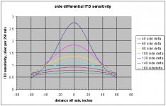
Here is a repeat of the side differential ITD sensitivity graph. On it are 7 lines, each line represents a source that is a specific distance away from the plane of the listener. That would be the "Y" direction in space relative to the listener...
The "X" direction in space represents the distance away from the midplane of the listener. The graph states that as distance off axis..
X and Y form the two dimensional orthogonal grid that I am using to define the source location in space.
On this graph, the vertical axis is ITD sensitivity per 1/4 inch..I used 1/4 inch to provide smooth curves for the plot.
To read this graph, an example..
For a source that is 60 inches away, the violet curve pertains.
For a source that is on axis, the violet line crosses at 1.8 uSec..that means, that a source on axis that moves 1/4 inch to the right or left, will cause an ITD shift of 1.8 uSec. If it moves 1 inch, it will cause an ITD shift of 4 times 1.8, or 7.2 uSec.
Now, examine a systemm that is being used to project a virtual image in space. If the system is absolutely accurate, there will be no interchannel delays and the ITD will be zero. The image will be on axis. If the system introduces a delay in one speaker of 7.2 uSeconds, the image will have appeared to shift one inch sideways towards the speaker which is first.
As to your distance question, note for example, the 160 inch distance line, which is blue-green. One inch shift is about .7 uSec times 4, or 2.8 uSec. This means that the virtual image accuracy further away, is more sensitive to ITD shift.
As I stated initially, this analysis derives exactly what arrives at the ears from a point source in space. It does not state that we can localize an object 160 inches away to within one inch..it states the reproduction system requirements if you wish to do so.
The IID graphs are the same kind of analysis..however, the combination of ITD and IID can be used to establish depth sensitivity, as the curves are not co-axial, nor are they orthogonal.
Further analysis will establish the system limits on ITD and IID errors that can be tolerated while simulating a point in space with a physical error band, I chose arbitrarily a one foot radius circle around the source for textual descriptors.
Cheers, John
soongsc said:
How far is the image from the listener? If the image is 6 feet from the listener versus 20 feet from the listener, it makes a difference.
Suppose the image moves from 20 feet away from the listener to 21 feet from the listener, but in the same direction, wouldn't ITD and IID be pretty much the same? At least the change would be different if the image moved sideways along the 20 feet radius with the listener at the center of it.
I will again attempt to explain..perhaps this time I will be clearer.😕
Here is a repeat of the side differential ITD sensitivity graph. On it are 7 lines, each line represents a source that is a specific distance away from the plane of the listener. That would be the "Y" direction in space relative to the listener...
The "X" direction in space represents the distance away from the midplane of the listener. The graph states that as distance off axis..
X and Y form the two dimensional orthogonal grid that I am using to define the source location in space.
On this graph, the vertical axis is ITD sensitivity per 1/4 inch..I used 1/4 inch to provide smooth curves for the plot.
To read this graph, an example..
For a source that is 60 inches away, the violet curve pertains.
For a source that is on axis, the violet line crosses at 1.8 uSec..that means, that a source on axis that moves 1/4 inch to the right or left, will cause an ITD shift of 1.8 uSec. If it moves 1 inch, it will cause an ITD shift of 4 times 1.8, or 7.2 uSec.
Now, examine a systemm that is being used to project a virtual image in space. If the system is absolutely accurate, there will be no interchannel delays and the ITD will be zero. The image will be on axis. If the system introduces a delay in one speaker of 7.2 uSeconds, the image will have appeared to shift one inch sideways towards the speaker which is first.
As to your distance question, note for example, the 160 inch distance line, which is blue-green. One inch shift is about .7 uSec times 4, or 2.8 uSec. This means that the virtual image accuracy further away, is more sensitive to ITD shift.
As I stated initially, this analysis derives exactly what arrives at the ears from a point source in space. It does not state that we can localize an object 160 inches away to within one inch..it states the reproduction system requirements if you wish to do so.
The IID graphs are the same kind of analysis..however, the combination of ITD and IID can be used to establish depth sensitivity, as the curves are not co-axial, nor are they orthogonal.
Further analysis will establish the system limits on ITD and IID errors that can be tolerated while simulating a point in space with a physical error band, I chose arbitrarily a one foot radius circle around the source for textual descriptors.
Cheers, John
Attachments
Re: Re: Re: Reply to Original Posted Question
No, they were all on the money, as you prefaced the first post with "part 1". I simply read both posts. I also have to live within the size limitation imposed by this forum.
As stated, nothing was ignored.
We are, of course, not discussing "lateralization"....we are discussing "localization". That is why I chuckled a while ago when you promised over at AA to explain how speaker wire affected lateralization far "differently" than I was talking about..
I will again provide definitions..
Lateralization is defined as the imaging of sound WITHIN the head. It is a result of headphone stimulus, and forces the virtual image formed to be ON the lateral line, this line being a straight line from ear to ear. It does NOT refer to a virtual image which is located outside the confines of the human head..
Localization is defined as the "locating" of a source in space, outside the head....front, back, side...but, not on the lateral line between the ears.
You do not "lateralize" an image produced by two speakers that are physically off the lateral line. You do not localize an image when the reproducers are on the lateral line..
Hmmm..a non peer reviewed three part article in an audio magazine.. It might be an interesting read. What is his premise?..the title doesn't float my boat..I hate it when authors try to sell papers with sensationalism..
The last non peer reviewed article from an audio magazine I read in detail, was that hugely incorrect skin effect paper by Hawksford..
I also have a really interesting article from a non peer reviewed mag in which a guy "proved" faster than lightspeed propagation in wires...and it wasn't april's issue..
Cheers, John
Hey, any moosetracks lately?
Jon Risch said:
As I stated at the very end (of the Part 2 post, I had to break it up into two parts due to the word length limitation here) I was not yet specifically addressing your theories, so all the comments you made were superfluous or unwarranted.
No, they were all on the money, as you prefaced the first post with "part 1". I simply read both posts. I also have to live within the size limitation imposed by this forum.
Jon Risch said:
I will grant that my statement did come at the end of "Part 2", so I will assume that you were eager to respond, rather than ignoring that statement..
As stated, nothing was ignored.
Perhaps, if and when we discuss lateralization, the issues inherent with that will be considered..Jon Risch said:All the observations I have made have been without SPECIFICALLY considering lateralization isues. I am not convinced that laterallization is the ONLY factor that would render cable parameters and issues relevant to high performance playback, I rather think that it is one of several factors to be examined...
We are, of course, not discussing "lateralization"....we are discussing "localization". That is why I chuckled a while ago when you promised over at AA to explain how speaker wire affected lateralization far "differently" than I was talking about..
I will again provide definitions..
Lateralization is defined as the imaging of sound WITHIN the head. It is a result of headphone stimulus, and forces the virtual image formed to be ON the lateral line, this line being a straight line from ear to ear. It does NOT refer to a virtual image which is located outside the confines of the human head..
Localization is defined as the "locating" of a source in space, outside the head....front, back, side...but, not on the lateral line between the ears.
You do not "lateralize" an image produced by two speakers that are physically off the lateral line. You do not localize an image when the reproducers are on the lateral line..
Ah, then an interesting coincidence...good enough..Jon Risch said:Thus, my statement about one dimensional and multi-dimensional has absolutely NOTHING to do with lateralization, but rather, the fact that I was refering to one dimensional metrics vs. multidimensional reality.
Jon Risch said:If you can get ahold of a copy, see:
Heyser, Richard C.;"Catastrophe Theory and It's Effect On Audio", Parts 1 thru 3, Audio magazine, March, April, May 1979
It should be available in many major libraries on microfilm or microfiche.
Jon Risch
Hmmm..a non peer reviewed three part article in an audio magazine.. It might be an interesting read. What is his premise?..the title doesn't float my boat..I hate it when authors try to sell papers with sensationalism..
The last non peer reviewed article from an audio magazine I read in detail, was that hugely incorrect skin effect paper by Hawksford..
I also have a really interesting article from a non peer reviewed mag in which a guy "proved" faster than lightspeed propagation in wires...and it wasn't april's issue..
Cheers, John
Hey, any moosetracks lately?
Re: Re: Re: Re: Re: Re: Reply to Original Posted Question
So it's the geometric distance difference the image is between the left and right ear that is used to determine ITD and IID, should be easy with Excel. It looks comlicated when you plot the data like that. This could be used to determine ideal energy distribution pattern of drivers so that the image stability can be acheived in a wide sweet spot.
jneutron said:
I will again attempt to explain..perhaps this time I will be clearer.😕
Here is a repeat of the side differential ITD sensitivity graph. On it are 7 lines, each line represents a source that is a specific distance away from the plane of the listener. That would be the "Y" direction in space relative to the listener...
The "X" direction in space represents the distance away from the midplane of the listener. The graph states that as distance off axis..
X and Y form the two dimensional orthogonal grid that I am using to define the source location in space.
On this graph, the vertical axis is ITD sensitivity per 1/4 inch..I used 1/4 inch to provide smooth curves for the plot.
To read this graph, an example..
For a source that is 60 inches away, the violet curve pertains.
For a source that is on axis, the violet line crosses at 1.8 uSec..that means, that a source on axis that moves 1/4 inch to the right or left, will cause an ITD shift of 1.8 uSec. If it moves 1 inch, it will cause an ITD shift of 4 times 1.8, or 7.2 uSec.
Now, examine a systemm that is being used to project a virtual image in space. If the system is absolutely accurate, there will be no interchannel delays and the ITD will be zero. The image will be on axis. If the system introduces a delay in one speaker of 7.2 uSeconds, the image will have appeared to shift one inch sideways towards the speaker which is first.
As to your distance question, note for example, the 160 inch distance line, which is blue-green. One inch shift is about .7 uSec times 4, or 2.8 uSec. This means that the virtual image accuracy further away, is more sensitive to ITD shift.
As I stated initially, this analysis derives exactly what arrives at the ears from a point source in space. It does not state that we can localize an object 160 inches away to within one inch..it states the reproduction system requirements if you wish to do so.
The IID graphs are the same kind of analysis..however, the combination of ITD and IID can be used to establish depth sensitivity, as the curves are not co-axial, nor are they orthogonal.
Further analysis will establish the system limits on ITD and IID errors that can be tolerated while simulating a point in space with a physical error band, I chose arbitrarily a one foot radius circle around the source for textual descriptors.
Cheers, John
So it's the geometric distance difference the image is between the left and right ear that is used to determine ITD and IID, should be easy with Excel. It looks comlicated when you plot the data like that. This could be used to determine ideal energy distribution pattern of drivers so that the image stability can be acheived in a wide sweet spot.
jneuron,
Before you dig deep again into ITD and ILD based modelling, consider the accuracy of the ITD and ILD only localization, the "cone of confusion", the importance of spectral clues, the party effect etc. Your model is too simple and gives falsely high resolution.
Minimum detectable ITD is around 1-2 deg at 200 Hz and getting worse with the increase of the frequency. Above around 1kHz ITD is useless ( 20 deg error), because the head size approaches half wawelength and the perceptually storng IPD clues confused.
ILD only error is around 5-10 deg.
Re: Re: Re: Re: Re: Re: Re: Reply to Original Posted Question
Correct. And it indeed was easy with excel, that is the program I used for the presented graphs.
Doing the equations in two dimensions with one inch resolution is much more difficult, it would require a matrix of cells 120 by 120, within each cell, the maxima of ITD and IID calculated along a radius of length from the cell location. It is much easier building VB code with nested loops...in fact, the hardest thing using VB is the 3 D graphics with color vs scalar value. at least I have code blocks for the graphics now.
One of the most significant issues with complex problems is the presentation of results.. Rather than presenting the dataset in a four dimensional fashion, I present individual entities for now. Additionally, the matrix algebra needed to map from one co-ordinate system to another, I ignore for now..but eventually that will need to be addressed to map from a point source to the ears, and back to two speakers....after all, this entire calc set is from the speakers to the virtual image, and the inversion matrices are easily calculated from the mapping
Bose did that years ago.
They rely on the reflection characteristics of the two plane array. If you think about it, you will realize that the reflection direction we get from one speaker changes with time, moving outward without doppler. This is interpreted by humans as a larger image, and indeed increases the "sweet spot". But it doesn't necessarily increase the image stability, it just makes the image larger than the system image stability..."if the spot is vibrating, de-focus.."
It unfortunately increases the image size, which some find annoying.. but allows more people to enjoy a good image..
soongsc: it is indeed a pleasure discussing this with you..thank you.🙂 🙂 🙂
Cheers, John
soongsc said:
So it's the geometric distance difference the image is between the left and right ear that is used to determine ITD and IID, should be easy with Excel.
Correct. And it indeed was easy with excel, that is the program I used for the presented graphs.
Doing the equations in two dimensions with one inch resolution is much more difficult, it would require a matrix of cells 120 by 120, within each cell, the maxima of ITD and IID calculated along a radius of length from the cell location. It is much easier building VB code with nested loops...in fact, the hardest thing using VB is the 3 D graphics with color vs scalar value. at least I have code blocks for the graphics now.
You are a master of understatement.😀 😀 😀soongsc said:It looks comlicated when you plot the data like that.
One of the most significant issues with complex problems is the presentation of results.. Rather than presenting the dataset in a four dimensional fashion, I present individual entities for now. Additionally, the matrix algebra needed to map from one co-ordinate system to another, I ignore for now..but eventually that will need to be addressed to map from a point source to the ears, and back to two speakers....after all, this entire calc set is from the speakers to the virtual image, and the inversion matrices are easily calculated from the mapping
soongsc said:This could be used to determine ideal energy distribution pattern of drivers so that the image stability can be acheived in a wide sweet spot.
Bose did that years ago.
They rely on the reflection characteristics of the two plane array. If you think about it, you will realize that the reflection direction we get from one speaker changes with time, moving outward without doppler. This is interpreted by humans as a larger image, and indeed increases the "sweet spot". But it doesn't necessarily increase the image stability, it just makes the image larger than the system image stability..."if the spot is vibrating, de-focus.."
It unfortunately increases the image size, which some find annoying.. but allows more people to enjoy a good image..
soongsc: it is indeed a pleasure discussing this with you..thank you.🙂 🙂 🙂
Cheers, John
My model is not about human hearing capabilities yet..fcserei said:jneuron,
Before you dig deep again into ITD and ILD based modelling, consider the accuracy of the ITD and ILD only localization, the "cone of confusion", the importance of spectral clues, the party effect etc. Your model is too simple and gives falsely high resolution.
It is about what arrives at the ears from a source in space, regardless of where in the soundfield it comes from. It also ignores height, front/back, spectral sensitivity, and absolute levels..
The model affords resolution to the nanoinch level..depending on the math precision...this I stated many posts ago, and I also stated not to confuse the calculations presented with human capabilities..it uses an IDEAL receiver for now..human capabilities must be overlayed upon this model to see what is actually important within the soundstage volume..
fcserei said:
Minimum detectable ITD is around 1-2 deg at 200 Hz and getting worse with the increase of the frequency. Above around 1kHz ITD is useless ( 20 deg error), because the head size approaches half wawelength and the perceptually storng IPD clues confused.
ILD only error is around 5-10 deg.
Your statements are not consistent with all the research papers I have found..do you have anything to support this which you could present?
It seems you are presenting sine data..as what you say is indeed consistent with that..many researchers have discussed and measured the "half wavelength" confusion you point out. That is not what I am discussing..
Cheers, John
Re: Re: Re: Re: Re: Re: Re: Re: Reply to Original Posted Question
This also reminds me of another array of drivers I saw a few days ago. The design is supposed to give you surround sound without puting speakers around your house. It works like the inverse of a phase array radar with an array of drivers that's supposed to be located on top of your TV. It's hard to beleive an array of little speakers can do that, I look forward to giving it a listening test.
Actually I also enjoy the opportunity to practice on improving my communication skills. 😱 😱 😱 Thanks for the encouragement.🙂
jneutron said:
Bose did that years ago.
They rely on the reflection characteristics of the two plane array. If you think about it, you will realize that the reflection direction we get from one speaker changes with time, moving outward without doppler. This is interpreted by humans as a larger image, and indeed increases the "sweet spot". But it doesn't necessarily increase the image stability, it just makes the image larger than the system image stability..."if the spot is vibrating, de-focus.."
It unfortunately increases the image size, which some find annoying.. but allows more people to enjoy a good image..
soongsc: it is indeed a pleasure discussing this with you..thank you.🙂 🙂 🙂
Cheers, John
This also reminds me of another array of drivers I saw a few days ago. The design is supposed to give you surround sound without puting speakers around your house. It works like the inverse of a phase array radar with an array of drivers that's supposed to be located on top of your TV. It's hard to beleive an array of little speakers can do that, I look forward to giving it a listening test.
Actually I also enjoy the opportunity to practice on improving my communication skills. 😱 😱 😱 Thanks for the encouragement.🙂
Reply to Original Posted Question, Part 3
I have attempted to answer some of the questions asked by the original poster, but that still had some other potential issues left unasked.
1. There are cable parameters associated with the fundamental L,C, and R parameters. These could be called secondary and tertiary parameters. One example is Dielectric Absorption, which is a capacitance related parameter.
Most DA measurements depend on a DC type of measurement, as a simple way of determining the total extent of the longer RC time constants that correspond to the model of the DA mechanism.
However, the signal aberrations that occur with an audio signal are the result of the constantly changing AC audio signal, and the failure of the dielectric to fully absorb all of the signal fast enough, and then upon a discharge situation, to fully release that charge quickly enough. What this leads to is often overlooked entirely, and that is that the signal aberrations are now signal history dependent, and the amount and nature of the signal aberrations are dependent on what has gone before, and where it came from.
Thus, the DA as determined by the common MIL spec method using DC, will seldom provide the full measure of the amount of signal aberration as it applies to an audio signal.
REF:
Pease, Robert A.; "Understand capacitor soakage to optimize analog systems." http://www.national.com/rap/Application/0,1570,28,00.html
Jung, Walt & Marsh, Richard N.; "Picking Capacitors",
http://www.capacitors.com/picking_capacitors/pickcap.htm
Marsh, Richard N., "Considerations for a High Performance Capacitor"
http://www.capacitors.com/picking_capacitors/consider.htm
Note on Cap D-E curves, by Steve Bench:
http://members.aol.com/sbench102/caps.html
http://members.aol.com/sbench102/caps1.html
http://members.aol.com/sbench102/caps2.html
Karl A. Weber, "On Capacitor Dielectric Materials - A Chemist's View"
http://audience-av.com/on_capacitor_dielectric_material.htm
"A Real-Time Signal Test for Capacitor Quality", by John Curl and Walt Jung, The Audio Amatuer, 4/85 pp 22-24
2. Vibrations
This is a controversial topic, and one prone to misunderstanding and the usual highly charged arguments. I ask that everyone take a moment to put aside their preconceptions and any biases they may already have, and read this with an open mind.
There is no doubt that audio cables are exposed to significant vibration, they are almost always used within the same room that the playback event is occurring in, and are exposed to the very music they carry the signal for.
There are two basic aspects of vibration I will look at there:
self-induced vibrations, and the results of external vibrations.
As I note in this post, about 1/2 way down, under the heading Resonances:
http://www.AudioAsylum.com/audio/cables/messages/2341.html
there is what has been commonly referred to as magnetostriction in audio cables, but since the actual conductor material is not really expanding and shrinking with the signal intensity or the vibration, it is more of an overall cable assembly kind of thing, and therefore, I have been calling it motor/generator action.
The cable has a signal passing through it, this generates a magnetic field for each current carrying conductor, which then generates a force on any other nearby wires also carrying current. This force could then cause the wires to move relative to one another, and if they move while inside a magnetic field, there will be a voltage generated within them. Thus, the original signal would have the potential to create a spurious signal within the cable.
Many arguments have been made over this potential effect, and one of them is that the spurious signal would be canceled out by the original signal. This overlooks several impediments to this occurring, namely that the resultant spurious signal would not be a replica of the original, but a half-wave rectified version of it (note there are no diodes involved, but rather the stress and relaxation motion of the conductors is what causes this), and that the motion of the conductors is not going to be completely in step with the original signal, as the motion that occurs will be out of sync with the original stimulus signal due to the delay in acceleration and motion of the conductors.
Another popular argument against the motor/generator effect is that the spurious signal will be so small, because the wires can not move enough to generate any significant voltage.
This is more in the nature of one of those "I have decided that the spurious signal level is too low to bother with" arguments. There is no doubt that motor/generator can take place, that IF the wires move, there WILIL be a voltage generated. The only question is that of how large will this spurious signal be.
As I noted in Part 1 of these posts, I feel that signal aberrations down to -90 dB and below need to be taken into account, rather than some much higher levels. As far as I am concerned, no one has really shown with any amount of certainty, that the raw motor/generator activity is too low to be a possible distortion source.
The second aspect is that even if we can come to some sort of fairly certain assessment that the direct motor/generator action is too low to be audible distortion, there is the matter of the acoustic sounds within the room, and the vibration of the wires by the external sounds. Note tha the amount of delay for this stimulus is MUCH larger than for the direct motor/generator activity, the sound travel time in the air is involved, and so, the spurious signals are no longer a half-wave rectified type version of the original signal, but are now convoluted with the time delay of the airborne sound waves, and whatever signal is now currently passing through the cables. The magnetic field present in the wires is no longer even remotely signal correlated with the vibrations, except via a very long history aspect.
As far as I know, no one at all has ever addressed the possible signal levels that might be present with this kind of situation.
It is also noteworthy to realize that a simple bench test of a cable, with out any significant level of sound waves present, will not even be able to test for this effect.
REF:
http://www.soundstage.com/maxdb/maxdb011999.htm
3. RF Resonance
Audio cables consist of lengths of wire, they can easily become antenna's, and can even become accidentally tuned to some specific frequency, exhibiting antenna gain.
Each cable will react differently with a given component, each SYSTEM will synergize differently with each individual cable within the system. Change out ONE cable, and you may have altered, created, or removed a troublesome RF resonance, and thus, altered the sound of the system.
Are ferrite beads/clamps a universal cure? Sometimes the cure is worse than the disease, and can lead to increased inductance, electrical resonances at a different frequency (usually much lower than without the bead/clamp).
Cardas, George; "Cable Resonance is Easy to Measure",
http://www.cardas.com/insights/measureresonance.html
Synergizing with Greg Weaver, May 1998
"Ferrite"-ing Out RFI
http://www.soundstage.com/synergize/synergize051998.htm
4. Metallurgy
he metallurgy of a cable includes not only the main cable wire conductor, but the terminations, as well as any interface between them.
Whether crimped, soldered, or merely bare stranded wires held (loosely) in a 5-way binding post, the connection is not a trivial aspect of a speaker cable.
I found through my own controlled listening tests, that the connection at the amp and at the speaker has to be consistent and low resistance in order for cables to be compared accurately and to get any kind of significant results.
It might be surprising to some to find that just cramming some stranded wire under a 5-way binding post, and hand tightening DOES NOT achieve a low resistance connection. In fact, doing so at both ends of the cable could result in as much or more resistance that the entire cable itself. Unfortunately, this connection invariably degrades over times, and with exposure to...... vibration.
It gets worse, not better, and sometimes it gets worse relatively quickly, depending on the atmospheric conditions present.
In order to assure a good solid and long term connection at a speaker cable, both the power amp and the speaker connections should be via a spade lug, and wrench tightened down till you can not loosen them by hand. The connection between the spade and the wire should be so good, that the wire itself will tear and fail first, rather than come apart at the crimp or solder joint.
Commercial cables use a variety of termination methods, of varying quality, and thus, the sonic accuracy of the cables can vary, even when the binding post has been properly tightened.
Cont'd in Part 4
NOTE: This is still not specificaly addressing jneutron's theories.
Jon Risch
Reply to Original Posted Question, Part 4
Part 4
5. EM Field Distortion
This is as much a geometry thing as it is anything else. How close are other materials, such as a grounded component chassis, or a large chunk of steel in a rack? Is the cable laying on carpet, what is the floor made of under the carpet, etc.
Along those same lines, how close is the shield of a twisted pair, is it so close that the EM field is significantly distorted? Knowing that even a well constructed twisted pair will have some magnetic field radiation pattern, and the electric fields will inevitably radiate out into space, the presence of a shield that is within a few inches will distort the EM field somewhat, and when we are talking about cables that have shields within a fraction of an inch, and they ALL vary in how close they come to the twisted pair wires, then we have a situation where the sound of the cable could vary due to something as relatively innocuous as how much closer, or farther away, the shield braid (or foil) is.
Some folks want to pretend that the coaxial cables have no such problems, that the magnetic fields are contained within the coax, or excluded from without totaly and completely. Yet the magnetic fields can penetrate the coax braid, and can be measured, even a portion of the electric field can penetrate the shield braid (90 or 95 or even 98% coverage is not 100%), and be affected by, or affect another cable or signal.
The so-called center wire does not always travel down the exact center of the coax braid, even when the cable is in a relaxed, more or less straight condition, much less when it is bent. Thus any EM field cancellation we are expecting to nullify are not going to be perfect, and it takes a very very small deviation to allow signal levels above -90 dB to get through.
REF:
Simulations of EM fields for different cable geometry’s.
http://www.geocities.com/jonrisch/emf1.htm
Why elevating cables off the floor may have an effect.
http://www.AudioAsylum.com/audio/cables/messages/60272.html
6. Biwiring versus Single Wiring
There are different topologies available to wire up a speaker, this is explored at the below referenced web pages. I encourage you to read all of the material, especially the 2nd and 3rd pages, where something much more advanced than the usual biwiring arguments is explored.
http://www.geocities.com/jonrisch/biwiring.htm
AND
http://www.geocities.com/jonrisch/biwiring2.htm
http://www.geocities.com/jonrisch/biwiring3.htm
Also, I wish to comment on one of the other common arguments about playback system component audibility, and this is applicable to any of the components in a playback system, including the cables.
See:
Using Up the Error Budget in the Studio:
http://www.audioasylum.com/audio/cables/messages/30013.html
Finally, I want to mention that DBT, or Double Blind Listening tests, are often brought up as if they were definitive "evidence" that audio cables do not sound different. These are often considered as if they were some sort of 'proof' that cables sound alike.
But if we follow the true tenants of science, then we must all realize, that a mere handful of amatuer listening tests with known flaws and problems, that happend to come up with statistically 'null' results, really aren't very good evidence of anything, much less such a definitive conclusion as they are often attempted to be used to back up.
In point of fact, these isolated amatuer listening tests provide no real evidence of anything at all, much less as proof or evidence that there are listening test results that show a 'negative' for audio cable sonic differences.
See:
http://www.audioasylum.com/forums/prophead/messages/2190.html
http://www.audioasylum.com/forums/prophead/messages/2579.html
http://www.audioasylum.com/forums/prophead/messages/2580.html
for some discussion of the various flaws and problems that were present in most of the amatuer listening tests often cited as if they were evidence.
There have been popular press articles that came up with positives for audio cable sonic differences using blind test procedures, several of which have been published by Home Theater magazine (Brent Butterworth), and several more by the British magazine, Hi-Fi News & RR.
REF:
Blind tests of Speaker Cables, Home Theater mag.
http://www.sonic.net/soundscape/wire_rev.html
http://www.ozenterprises.net/wire/icacbles.pdf
Butterworth, Brent & Griffin, Al 'String 'em Up!' Home Theater, Oct 98
Butterworth, Brent 'Walking the High Wire,' Home Theater, Nov 98, pg 94-102.
My own listening test efforts have also resulted in positives for cable differences, and while I have not published the listening test results formally, I do make the conclusions available in the form of my DIY notes on constructing high performance audio cables inexpensively.
See:
http://www.geocities.com/jonrisch/i1.htm
and
http://www.geocities.com/jonrisch/s1.htm
I have presented my listening test methods to the AES.
My AES paper is preprint #3178, "A User Friendly Methodology for Subjective Listening Tests", presented at the 91st AES convention, October, 1991.
Consisting of 33 pages of text, and 19 references, it is too long to try and present here, and I urge anyone interested in the details to get a copy from the AES, it is available for $5, and can be ordered from:
http://www.aes.org/publications/preprints/search.html
I also can make it available as a text file, to anyone who e-mails me and requests a copy.
j_risch@bellsouth.net
Jon Risch
- Status
- Not open for further replies.
- Home
- General Interest
- Everything Else
- Technical discussion on loudspeaker cable