Hi all. I am looking to install an external antenna on my TDA 7492. Normally, I would just cut the trace and solder a 31.25mm copper wire but this amp will be behind 1/2" oak and some other interference so I need an extended antenna mounted outside my enclosure.
I know will need a ground for the shield of my coax. Will the indicated ground from the datasheet serve as a suitable ground?
I know will need a ground for the shield of my coax. Will the indicated ground from the datasheet serve as a suitable ground?
Attachments


Well, I'm just going to go for it and see if my range increases, decreases or stays about the same. Seems pretty low risk.
You might want to cannibalize an old 2.4Ghz antenna and SMA connector and coax from an old throwaway 802.11b router. That ground would be fine but need to cut the trace to the strip line antenna.
Do you have a link for this board?
Do you have a link for this board?
Well, if you look at the pcb, this pin is not GND but the external antenna pin. You'll need to set over the resistor on board. Maybe some tuning to the antenna is needed then. Quite similar to 8645 boards i have.
Last edited:
I have a TDA7492 bluetooth board just glued to the side of an aluminum speaker box and it makes no difference how I orientate it.
You perhaps should cover your board with a few lumps of timber and see what happens, before any cabinet making.
You perhaps should cover your board with a few lumps of timber and see what happens, before any cabinet making.
@xrk971: Yes, I plan on soldering a U.FL connector in there so I have plenty of antenna options. Ebay is flooded with these, just search "TDA7492P Bluetooth". This is the particular model I have. The temporary switches on the red version have this weird 3rd leg and I cannot figure out how to use external switches (I will be routing my buttons to the top of the box for music controls).
@xrk971: Could you explain what you mean by "set over the resistor on board"? I think I see what you are saying with the GND pin routing through a resistor over the start of the active antenna.
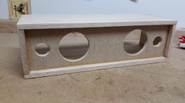
@radiosmuck: Thanks, but having it mounted inside and having a simple looking, clean build are important to me, so I don't want to mount is outside. I've already built the basic frame. Also, the thick oak is really dense and I am losing range in stock configuration.
@xrk971: Could you explain what you mean by "set over the resistor on board"? I think I see what you are saying with the GND pin routing through a resistor over the start of the active antenna.
@radiosmuck: Thanks, but having it mounted inside and having a simple looking, clean build are important to me, so I don't want to mount is outside. I've already built the basic frame. Also, the thick oak is really dense and I am losing range in stock configuration.
Attachments
Last edited:
Did had a look again into this, the CSR8635 is different at this area and this pin is truely GND.
Fitting an u.FL there might work like on the image attached.
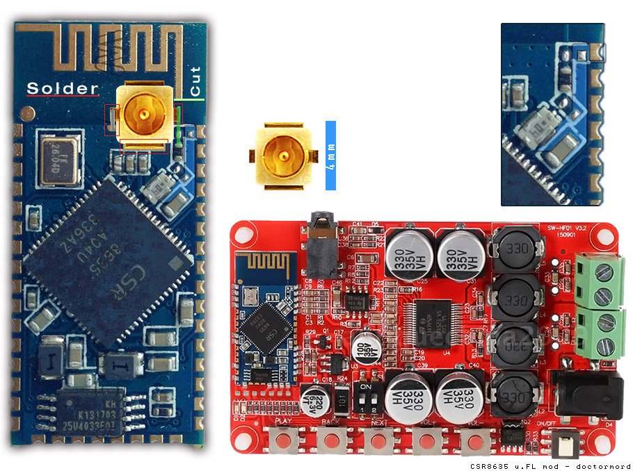
So cutting the board antenne, scratch off the traces silkscreen and some area of the groundplane, solder the u-FL tip and one side of the screen and optional attach a piece of wire to the "spare" pin on the left. Due to the trace is now going 90° to the u.fl, tuning might be needed. the already fittet resistor plus the 2 free 0402 footprints forms a pi-arrangement.
Fitting an u.FL there might work like on the image attached.
So cutting the board antenne, scratch off the traces silkscreen and some area of the groundplane, solder the u-FL tip and one side of the screen and optional attach a piece of wire to the "spare" pin on the left. Due to the trace is now going 90° to the u.fl, tuning might be needed. the already fittet resistor plus the 2 free 0402 footprints forms a pi-arrangement.
Attachments
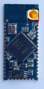
Thanks doctormord. This is really helpful. I like pictures! Might I benefit from turning the u-fl 90 degrees clockwise and soldering a 2-3mm jumper to the GND pin on the right and the scratched off ground on the board? Please excuse my grade level Paint skills.
Attachments
I see, everything in one box, including speakers?
Keeping the BT transmitter as close to the receiver as possible prevents problems, walking around with an iphone could be problematic.
Keeping the BT transmitter as close to the receiver as possible prevents problems, walking around with an iphone could be problematic.
Yeah, why not if its holding in place. 🙂 (Mechanical strength is reduced when mounted like so)
I wouldn't care so much about the 90° in this small scale either, esspecially if you wont tune your new antenna anyway.
You could even just solder a piggytail to SMA there. (covered by epoxy)
I wouldn't care so much about the 90° in this small scale either, esspecially if you wont tune your new antenna anyway.
You could even just solder a piggytail to SMA there. (covered by epoxy)
Last edited:
Check out Ebay, thousands of these boards have been purchased without problems, what are you expecting?Awesome, thanks doctormord. I should get the amp soon and I'll reply back with some range info.
? What's the intent of your post?
If it works for you, does it mean it works for him? Keeping transmitter/receiver close together isn't always possible and getting some range out of a Bluetooth connection should be the goal. 🙂
Pretty much all enclosures detune an antenna, but ymmv.
Even if they sell thousands of boards, does this mean they are perfectly made? Having an Antenna not at the boards outside isn't something I'd call a good design.
Last edited:
I've bought more bluetooth receivers than I'd like to admit to. Some are definitely better than others, but by and large, they all benefit from an external, vertical dipole antenna mod. The PCB trace antennas are just in a terrible place with respect to optimizing range. So many bluetooth receivers will just drop out at 15 ft or so and it is a major pet peeve of mine so I tend to go a little overboard trying to extend range.
I also just enjoy tinkering and making something cheap that performs on the level of something more expensive.
I also just enjoy tinkering and making something cheap that performs on the level of something more expensive.
I use these with good success:
http://eu.mouser.com/search/ProductDetail.aspx?R=0virtualkey0virtualkey146186-0150
http://eu.mouser.com/search/ProductDetail.aspx?R=0virtualkey0virtualkey146186-0150
I use these with good success:
146186-0150 Molex | Mouser
Interesting, I have ordered a couple of these for use in my (2.4 GHz) r/c transmitter. I was going to see how it performs compared to an external dipole connected through SMA.
Airgain Built in Antenna N2420 IPEX U FL Feeder 3cm WiFi PCB Built in Antenna | eBay
The Airgain might be big better than the Molex at 2.4.G as they're pretty much tuned to this.The Molex is more wideband. From the pictures, the Airgain is a ground-referenced design, like the one on board, so enclosure might detune the antenna more than the Molex with isn't ground-referenced by design.
What did you end up doing and what were your results?
I have a similar bluetooth tpa3116 amp on the way, and I would like to extend the range..
If I replaced the printed antenna with a 3cm copper wire pointing upwards, how much would it improve my range - if it would at all? It is - pretty much like yours - going to be encased in 12mm plywood in a halfinator.
What did you end up doing and what were your results?
I have a similar bluetooth tpa3116 amp on the way, and I would like to extend the range..
If I replaced the printed antenna with a 3cm copper wire pointing upwards, how much would it improve my range - if it would at all? It is - pretty much like yours - going to be encased in 12mm plywood in a halfinator.
Well after I messed up my previous TPA7492 trying to solder the uFL receptacle, I ended up just not even bothering with the replacement one. I went with a TA2024 amp and this BT receiver. Its a better setup for me in every way, even though it cost me an extra $20. It has the uFL solder pads ready to go so I was able to add the receptacle on there no problem and I just cut the trace to the PCB antenna and added some double sided tape and tin foil to shield the exposed area a little. Additionally, it supports APT-X, has a mic, aux input, and a connection for external control buttons that actually works. Ill try and add a pic or 2
- Status
- Not open for further replies.
- Home
- Amplifiers
- Class D
- TDA7492 External Bluetooth Antenna