I was a bit late to the party, but since it only lasted a few seconds, then at least you know that your transformer had enough power. There was *probably* too much.
I like to size transformers at efficiency % multiplied by va = watts.
Like this: 0.62 * 36va = 22 watts so that LM1875 monobloc doesn't explode.
Alternatively: 0.62 * 400va = 248 watts so the amplifier can break (not recommended)
Tip:
Just parallel on enough output devices until the SOA capacity is higher than the transformer capacity -or- reduce the transformer capacity to Lower than the output device capacity. Basically, don't make constipated amplifier--don't put more power in than can come out.
Last edited:
hi, i got so much interest in your bridged amp but i have questions; what,s the value of resistors underneath the 6.8 resistor?, where do their leads go?, and there's a red jumper from the final stage of the amp to somewhere in between the amp where does it actually go?
pliz help i really need to try this one.
pliz help i really need to try this one.
These are 0,15R resistors. See the schematic in the previous page.
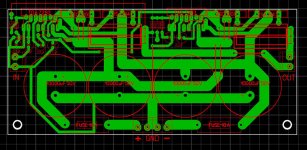
I used the pcb design by kebbz, provided by him on page 9.
The board i used, was just a bit smaller than needed for this design, so i had to run some tracks on top of the board.
I don't know what melted the woofer though🙁
I used the pcb design by kebbz, provided by him on page 9.
The board i used, was just a bit smaller than needed for this design, so i had to run some tracks on top of the board.
I'm currently under the impression that the amp is underpowered, based on the theoretical capabilities.There was *probably* too much.
I don't know what melted the woofer though🙁
Attachments
Try this high quality filter, in the speaker cabinet, close to the woofer, in series with the woofer negative. You can add a 10k resistor across it, from in to out, to help drain it eventually. This unit removes DC and some pointlessly low subharmonic pitches as well, so that your woofer probably won't melt from getting pushed really hard for non-audio tasks. This filter mostly prevents that problem. AND by not loading the amplifier severely for non-audio tasks, then your amplifier *may* be able to produce either slightly or lot more useful audio output.I'm currently under the impression that the amp is underpowered, based on the theoretical capabilities. I don't know what melted the woofer though🙁
Last edited:
That is like a trick question. 🙂 The difference between 115v rating versus 120v actual is that your 35vac transformer does 36.5+36.5vac and then 36.5vac*1.45=53vdc, so you have +-53vdc rails. Unfortunately, max operational supply range for TDA7293 is +-50vdc. And it is an unregulated supply, so given a very minor surge of 20%, you get +-64vdc. This is just too much higher than the maximum, so that amp will break sooner or later, the datasheet says she breaks at slightly over +-60vdc and therefore the answer to the wattage question is none/break.I have brought this transformer is it any good. what power could I get with two tda7293 chips two or three pairs of transistors
- 300VA TOROIDAL 2X35V
For that transformer, you don't want TDA7293 but rather what you need is an LME driver chip because those handle higher voltage. You'll be able to use your same outputs and all the other parts just fine. Now here goes with a guess: LME49810 (or LME49811) + 2SA1930/2SC5171 + 2SA1943/2SC5200, appears likely to work. A few searches with those LME part numbers should turn up some example projects.
I'll give it a try, when i find myself a new speaker. 🙂Try this high quality filter..
About this supply thing, I currently also have 240->2x35vac transformer, reading about +-52vdc after rectifying.
After reading your text, I'm thinking of making a 50v regulated supply, but being a noob, I rely on others to give me a schematic for this.
About this supply thing, I currently also have 240->2x35vac transformer, reading about +-52vdc after rectifying.
Well, actually, maximum is something we hope not to use. So, the typical transformers for TDA7293 are in the range of 28+28vac and lower.
A bit late response to JaanusJ.
First I want to say I'm happy he used my component layout. He asked earlier about the insulation of tda and transistors. You can only insulate 2SC5200 and mount TDA and 2SA1943 directly on the heatsink. But then you must insulate the heatsink from the amplifier case (box) cause it will be on the negative power supply line.
Also a hint: This amp needs a speaker delay circuit cause it has a nasty pop noise when you turn it on and some high pitch hiss noise when you power it off. So first power it on and then connect the speaker wire not to fry the speaker .... should of mention this before 😛
There is a nice and simple to build circuit with UPC1237 which offers speaker delay and protection. If someone has a tested PCB I would be glad if he could share it.
Last edited:
I just found this for those of you whom keep asking about using more output devices,
Amplificator cu TDA7294 si tranzistori | RoElectronica
I had covered those type of questions in a very early post in this thread.
I have not been able to get any of the output devices used as of yet so I have not tried this design, But I do plan to sometime in the future.
Cheers!!
jer 🙂
Amplificator cu TDA7294 si tranzistori | RoElectronica
I had covered those type of questions in a very early post in this thread.
I have not been able to get any of the output devices used as of yet so I have not tried this design, But I do plan to sometime in the future.
Cheers!!
jer 🙂
geraldfryjr i actually think that is one of the designs i stated out with a LONG time ago, but sounded like crap due to missing "sync" resistor
http://www.diyaudio.com/forums/members/geraldfryjr.html
http://www.diyaudio.com/forums/members/geraldfryjr.html
Bumping this thread, cause my amp kicked out some flames. I'm thinking lack of cooling to be the cause.
Anyway, new amp is almost ready.
But I have an idea of mounting the transistors on a separate radiator. Using actually 3 radiators in total, 1 for the chips and 1 for each transistor pair.
I do like to make things interesting, so will 2 of these be any good for the transistors?
ARCTIC | Alpine 20 PLUS CO | Intel CPU Cooler for Quietness | wide compatibility | quiet air cooling solution | efficient heat transfer | best performance | low noise | server cooling
Oh and is it still okay to mount the transistors away from the board using wires?
Well tbh, it did break a while ago. But thats all part of the diy process, I'm not worried, i like soldering😛
I've used a 30-0-30vac transformer and maintained an 8 ohm load and I have no problems, coz remember its a bridged amp and its already driving close to its maximum power, so if you increase load the more strain you're adding, more heat dissipation, so whatever load you add, maintain 8 ohms.if u want to drive more speakers try series- parallel connections
can someone tell me the heatsinks characteristics of the tda7294 and the two transistors ( 2sa1943 & 2sc5200) thanks a lot..
The 6,8 Ohm implies that the slew rate of the chipamp becomes critical. The chipamp only delivers around 100 mA output (makes 0,7 V over BE of the boost transistors).
It would be better if the Chaipamp delivers half its capacity, thus 3A. When assuming Ube = 0,7 V this implies that the R = 3/7 Ohm = 0,3 Ohm. If you use 0,5 Ohm, the chipamp will deliver 1,4 A and the boosters do the rest. This implies far less cross over distortion. I would like sombody test and measure the distorion.....
It would be better if the Chaipamp delivers half its capacity, thus 3A. When assuming Ube = 0,7 V this implies that the R = 3/7 Ohm = 0,3 Ohm. If you use 0,5 Ohm, the chipamp will deliver 1,4 A and the boosters do the rest. This implies far less cross over distortion. I would like sombody test and measure the distorion.....
- Home
- Amplifiers
- Chip Amps
- TDA7294 + Power Transistors AMP (TDA7293 to come also)