Attachments
Attachments

Hi Dr frost
greetings can you share any simple bridge amplifier circuit to bridge the amps
warm regards
andrew
greetings can you share any simple bridge amplifier circuit to bridge the amps
warm regards
andrew
This is the way i do it, but follow the TDA schematic and you can bridge them without opamps, and a few pages back someone posted a schematic of just that
Trimode Amplifier Bridging
Trimode Amplifier Bridging
Bridge can be found on page 9 of this thread where I posted the PCB layout. The key is to take the output from one module and via 22k resistor put it to pin 2 (inverted input) of the TDA in other module, also connect the pin 3 (non-inverting input) to the ground and that's all !
No need for additional op-amps, you just use the one found within the input stage of the TDA chip.
This is tested and works! Enjoy 😛
No need for additional op-amps, you just use the one found within the input stage of the TDA chip.
This is tested and works! Enjoy 😛
Last edited:
gev - nice one, even mosfet version 🙂
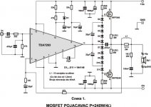
TDA7294 bridge (same on 93)
NOTE: quick google find and just schematic without transistors
kebbz can you post your schematic, if i find the time ill get on the job on editing post #1 to refer to your posts to get some system in this thread
TDA7294 bridge (same on 93)
An externally hosted image should be here but it was not working when we last tested it.
NOTE: quick google find and just schematic without transistors
kebbz can you post your schematic, if i find the time ill get on the job on editing post #1 to refer to your posts to get some system in this thread
Last edited:
Here, I had to edit the png image in photoshop to add the other components 🙂
An externally hosted image should be here but it was not working when we last tested it.
Hi dr frost,
I am building your design using tda 7253 and original toshiba transistors. i am not sure on how to determine the output of this circuit while using 25-0-25 @3 ampere current EI core CT transformer... i.e 150VA i am going to use it to drive subwoofers. but i am somewhat confused, i have 2x 4ohm 100w rms subwoofers. if i use the transformer, will it be able to deliver peak power of 100w into those 10 inchers in both? or should i drop the plan and use only one 4 ohm sub ? else, what is the power i can expect into 4ohm(single) 8ohm(series) loads and 2 ohm(paralell) loads with the given supply?
I am building your design using tda 7253 and original toshiba transistors. i am not sure on how to determine the output of this circuit while using 25-0-25 @3 ampere current EI core CT transformer... i.e 150VA i am going to use it to drive subwoofers. but i am somewhat confused, i have 2x 4ohm 100w rms subwoofers. if i use the transformer, will it be able to deliver peak power of 100w into those 10 inchers in both? or should i drop the plan and use only one 4 ohm sub ? else, what is the power i can expect into 4ohm(single) 8ohm(series) loads and 2 ohm(paralell) loads with the given supply?
Hello dr frost & all diyers
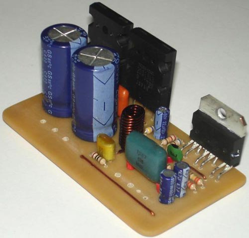
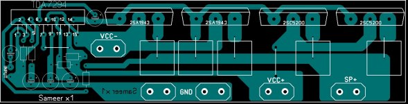
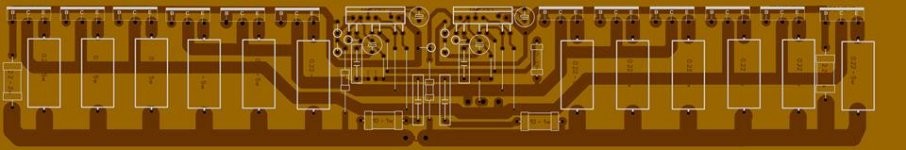
I still lay about amplifiers. and I am so excited to make this amplifier. I plan to make dual mono. This layout I would use. Please be corrected.


if any body have schematic opamp stereo/bridge with selector mode, please share .
I want to pair it with this amplifier.
Sorry if my English to bad.
I still lay about amplifiers. and I am so excited to make this amplifier. I plan to make dual mono. This layout I would use. Please be corrected.
if any body have schematic opamp stereo/bridge with selector mode, please share .
I want to pair it with this amplifier.
Sorry if my English to bad.
Hey koming, nice design. But the 22k resistor which goes to TDA pin 2 for the feedback loop, it does not go to pin 14 of the TDA, but after the two transistors so to the speaker connector. The rest seems fine.
Hi kebbz
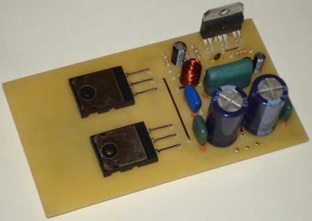
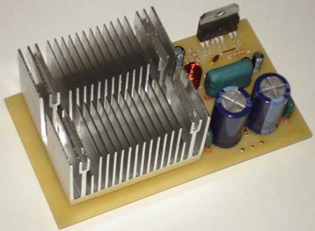
thanks already corrects my layout. i've fixed, hopefully it's ok now...


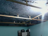
still for ground problems!
it awaits its turn! need a better camera.
it awaits its turn! need a better camera.
Attachments

Last edited:
I'd really like to make this, but i dont understand the way you power this. If you could please explain.
martin martinez in theory it should work with everything from OP-AMPS to any old-new home Amplifier, you just need the feedback (22K ohm in this case) and the "sync" resistor needs to be configured.
sameer x1 & koming looks good with the PCB, any plans to sell them?, my "hole print" thing works but it is easier to have a nice board with a good layout.
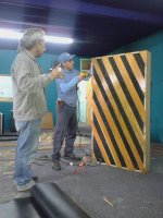
EDIT: andrewlebon THAT's quite an AMP!!!!, can't see if it is a stereo or just a bridged mono HIGH powered AMP
EDIT: It looks to be bridged so that AMP will push peak watts in excess of 2500W in 2 OHM!!!!
sameer x1 & koming looks good with the PCB, any plans to sell them?, my "hole print" thing works but it is easier to have a nice board with a good layout.
EDIT: andrewlebon THAT's quite an AMP!!!!, can't see if it is a stereo or just a bridged mono HIGH powered AMP
EDIT: It looks to be bridged so that AMP will push peak watts in excess of 2500W in 2 OHM!!!!
Last edited:
- Home
- Amplifiers
- Chip Amps
- TDA7294 + Power Transistors AMP (TDA7293 to come also)