Johnr66 I agree with you that experiment and make some measurements for this amplifier. But I consider that this schematic would look like amplifiers with output MOSFETs irfp240/irfp9240?
Cheers!
any one with a working schema to use with mosfets?
hi everybody
Its been a while, just want to report that the LM3886+5200/1943 amp at +-43.6V rails i doing just fine, good gain,good tone the chip is runnin just warm, the transistors a bit warmer-without the fan- sorry no pics, lost mycam.
the schem is the same gclone ptp with the 22k-1k-47uf fb string, 2x470uF at the chip, PS has single bridge rectifier then 2x2200uF parallel each polarity, then 3x1ohm parrallel each polarity then 2x2200uF parallel each pol. then +-V out and PS star ground.it sounds really good direct to rin or thru a 2.2 or 3.3 film cap.😎
do the transistors have to be isolated from the heat sink when put on the same heatsink with the ic??
I really want to try with 3875...
I even made PCB and ordered parts, i mostly fail at builind stuff from scrach so...
It can be faulty so help me to make it better.
how do you print screen
I even made PCB and ordered parts, i mostly fail at builind stuff from scrach so...
It can be faulty so help me to make it better.
An externally hosted image should be here but it was not working when we last tested it.
how do you print screen
output stage
have anyone tried this one
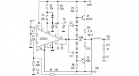
here is the total plan Electronics: 400 Watts High Power Output Amplifier
have anyone tried this one
here is the total plan Electronics: 400 Watts High Power Output Amplifier
Attachments
+-40Vdc supply, if regulated, could support a peak output of ~37Vpk into your speaker load.
8 ohms gets to 85W and 4ohms gets to 170W.
If the +-40Vdc sags to +-36Vdc, the maximum peak output will be ~33Vpk.
With 8ohms you get 60W and 120W into 4ohms.
The single pair output stage tends to support the 60W into 8ohms as the only sensible expectation.
Whoever states 400W is lying.
8 ohms gets to 85W and 4ohms gets to 170W.
If the +-40Vdc sags to +-36Vdc, the maximum peak output will be ~33Vpk.
With 8ohms you get 60W and 120W into 4ohms.
The single pair output stage tends to support the 60W into 8ohms as the only sensible expectation.
Whoever states 400W is lying.
have anyone tried this one
here is the total plan Electronics: 400 Watts High Power Output Amplifier
With that many diodes in the bias string, would expect it to start baking outputs in about 2 seconds.
Hi people! This time around to ask some questions, reading from these posts, i get different ideas as to how much power output to expect from my last amp, i tought i could get close to 2 thirds of the transformer rating? so maybe if it is 300 va, i have a chance to get 200w out? But then as you all know, there´s all these different comments here;and i get confused, being a self taught person. If i place a Vmeter across the outputs, while playing music -heavy bass and drums content, lots of sub and hi freq peaks-, What would i be reading? , and that how would translate to power output watts?
I´ll really apreciate your attention and comments
I´ll really apreciate your attention and comments
Attachments


The voltage is limited due to the TDA7293's limitations--see the datasheet. The transformer can be va 1.5x watts (from 500va to 750 va for 500 watt amplifier). Current handling may take about 4 pairs of output devices per each chip.
The current of TDA7293 can also be boosted with a multi-parallel arrangement using the slave pin 7 parallel tda7293 | eBay
The parallel fets give you a more powerful parallel amplifier without ballast resistor losses.
+-40Vdc supply, if regulated, could support a peak output of ~37Vpk into your speaker load.
8 ohms gets to 85W and 4ohms gets to 170W.
If the +-40Vdc sags to +-36Vdc, the maximum peak output will be ~33Vpk.
With 8ohms you get 60W and 120W into 4ohms.
The single pair output stage tends to support the 60W into 8ohms as the only sensible expectation.
Whoever states 400W is lying.
thanks for the reply
Is it possible to run this setup on a 18-0-18 transformer just for testing since I have one around ... Im guessing it is possible. Please excuse as im quite new to building amplifiers. Iv built a tda2030 bridged and a tda1554q(point to point) so far.Also i have ttc5200 and tta1943 that should be no problem ? The specs seem to be the same .
Last edited:
Is it possible to run this setup on a 18-0-18 transformer just for testing since I have one around ... Im guessing it is possible
It's possible and the output DC voltage after the bridge and the capacitor bank is gonna be around +-25VDC.
Also i have ttc5200 and tta1943 that should be no problem ? The specs seem to be the same .
They're the same as the 2SC5200/2SA1943 pair.
Best regards. 🙂
It's possible and the output DC voltage after the bridge and the capacitor bank is gonna be around +-25VDC.
They're the same as the 2SC5200/2SA1943 pair.
Best regards. 🙂
Thank you for the speedy reply.
I shall post after i build my first channel.
Regards
Joshdsy
Thank you for the speedy reply.
I shall post after i build my first channel.
Regards
Joshdsy
You're welcome 🙂 looking forward to see your project up and running.
If i use mica sheets for the ttc5200 and tta1943 and not the tda7294 is that ok as i would have to go to town just to get one mica sheet. I have everything else to start builing the first channel.
If i use mica sheets for the ttc5200 and tta1943 and not the tda7294 is that ok as i would have to go to town just to get one mica sheet. I have everything else to start builing the first channel.
Yes you can insulate the transistors only as long as the heatsink is for one channel and no more devices will be attached to it except for the transistor pair and the amplifier.
other possible solutions:
- split the mica sheet with a razor into two thinner insulators (ugly and troublesome).
- use a piece of PTFE tape (plumber tape) covered on both sides with thermal grease (make sure not to puncture the tape with any sharp edges on the heatsink or the IC's).
Best regards.
This heat sink is enough for both channels or only one ?
https://dl.dropboxusercontent.com/u/19464530/IMG_20131028_215534.jpg
https://dl.dropboxusercontent.com/u/19464530/IMG_20131028_215534.jpg
Here is a layout im thinking of using ... i haven't yet soldered.
https://dl.dropboxusercontent.com/u/19464530/IMG_20131028_222520.jpg
https://dl.dropboxusercontent.com/u/19464530/IMG_20131028_222520.jpg
- Home
- Amplifiers
- Chip Amps
- TDA7294 + Power Transistors AMP (TDA7293 to come also)