That was fast!
I see that the THD has improved slightly since the previous picture, but the SNR has dropped by 1dB!
You've obviously hit the "sweet spot" of the THD/SNR balance with the settings and results from @Dxvideos post#113 and your post#114,
which shows a result of 1Wrms/8R0 THD of 0.00093% and a SNR of 98.35dB
In my opinion, this is the OPTIMUM you can expect from this configuration/topology.
The results are very good now, indeed.
And, Now it's time to listen to the AMP prototype for a long time ...and get some impressions.
Best regards
Dragan
"Thanks for your support!
In my tests with 4.1mA, 4.6mA, and 5.6mA bias currents, the most pronounced second harmonic was observed at 5.6mA. After various optimizations, I found that the best feedback resistor values are 49.9kΩ and 4.99kΩ, yielding an SNR of 98dB and THD of 0.00115%—a significant improvement.
A slightly stronger second harmonic could contribute to a more musical and pleasing sound. I’ll be evaluating the amplifier with 5.6mA bias and 49.9kΩ/4.99kΩ feedback resistors in listening tests.
5.6mA 49,9k 4,99k graphic

I’m currently reviewing your last four THD distribution graphs,
and what stands out to me is the SNR result in the top-right corner of the graph in the last graph, your post ago!
What algorithm does QuantAsylum (QA) use to calculate SNR and THD%?
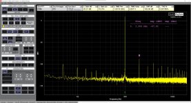
The 1 kHz carrier signal is 2.839 Vrms, which corresponds to +9.06 dBv (where 1V = 0 dBv).
Below the 1 kHz carrier signal, we also observe 50 Hz network interference and its higher harmonics.
This could be either direct interference or forced interference due to lowish PSRR.
The noise floor is seen at approximately <-130 dBv, which is quite uniform across the full bandwidth of 20 Hz to 20 kHz.
There is no increased noise at high frequencies from the TDA7293 output itself, as can be seen from the graph!
Everything is below the mentioned <130dBv !?
When we calculate the distortion sum (higher harmonics + 50 Hz hum) in correlation with the carrier signal at +9 dBv, we get a sum of 96.8 dBv.
If we exclude the lower frequencies below 1 kHz, then the sum is 98.1 dBv (I considered only the harmonics mentioned above), which QA also shows!
But this is effectively the THD(+N) in dB(v), which equates to about 0.00126%.
If we only consider the noise floor for the SNR and include all the interference from the home network and others,
then the displayed SNR is around 98.1 dBv.
However, this doesn’t represent our true picture of the SNR!
What would AQ show if you managed to shield the 50 Hz hum and its harmonics out of equation?
Have you measured the output noise voltage again with the input shorted?
@Dxvideo mentioned measuring around 18 µVrms of broadband output noise, which would give an SNR of around 104 dB @1Wrms@8R0 load.
This is almost the maximum expected for the TDA7293 used.
And it's a very good result, actually!
Cheers, Dragan
and what stands out to me is the SNR result in the top-right corner of the graph in the last graph, your post ago!
What algorithm does QuantAsylum (QA) use to calculate SNR and THD%?
The 1 kHz carrier signal is 2.839 Vrms, which corresponds to +9.06 dBv (where 1V = 0 dBv).
- Harmonic II: -92 dBv
- Harmonic III: -104 dBv
- Harmonic IV: -97 dBv
- Harmonic V: -103 dBv
- Harmonic VI: -106 dBv,
Below the 1 kHz carrier signal, we also observe 50 Hz network interference and its higher harmonics.
This could be either direct interference or forced interference due to lowish PSRR.
- 50 Hz: -90 dBv
- 100 Hz: -108 dBv
- 150 Hz: -102 dBv
- 200 Hz: -110 dBv
- 250 Hz: -108 dBv,
The noise floor is seen at approximately <-130 dBv, which is quite uniform across the full bandwidth of 20 Hz to 20 kHz.
There is no increased noise at high frequencies from the TDA7293 output itself, as can be seen from the graph!
Everything is below the mentioned <130dBv !?
When we calculate the distortion sum (higher harmonics + 50 Hz hum) in correlation with the carrier signal at +9 dBv, we get a sum of 96.8 dBv.
If we exclude the lower frequencies below 1 kHz, then the sum is 98.1 dBv (I considered only the harmonics mentioned above), which QA also shows!
But this is effectively the THD(+N) in dB(v), which equates to about 0.00126%.
If we only consider the noise floor for the SNR and include all the interference from the home network and others,
then the displayed SNR is around 98.1 dBv.
However, this doesn’t represent our true picture of the SNR!
What would AQ show if you managed to shield the 50 Hz hum and its harmonics out of equation?
Have you measured the output noise voltage again with the input shorted?
@Dxvideo mentioned measuring around 18 µVrms of broadband output noise, which would give an SNR of around 104 dB @1Wrms@8R0 load.
This is almost the maximum expected for the TDA7293 used.
And it's a very good result, actually!
Cheers, Dragan
Last edited:
Hello everyone;
We are approaching the final stage, and a significant improvement in SNR has been achieved, now reaching 103-102 dB. The dominant harmonic remains the second, with noise measuring at 17 µV and DC offset at 0.02 mV. The CCS is set to 4.7 mA.
@Dxvideo has begun critical listening tests and will share their impressions soon.
My initial observations: an exceptionally wide soundstage, pristine highs, and a well-balanced, highly detailed presentation.”
Attachments
My first impressions about the new version;
It has more detailed and more clinical sound than the old version. Wider stage and absolutely no audible noise or distortion at my listenning level!
Basses and mids are still balanced but sounded a bit bright to me.. (must be my personal opinion not an objective assesment)
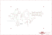
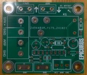
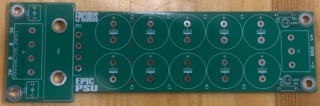
Sercan has already drawn the PCBs.. The final circuit will be;
Note : R15 should be 4K99 and R13-R14 = 240R..

It has more detailed and more clinical sound than the old version. Wider stage and absolutely no audible noise or distortion at my listenning level!
Basses and mids are still balanced but sounded a bit bright to me.. (must be my personal opinion not an objective assesment)
Sercan has already drawn the PCBs.. The final circuit will be;
Note : R15 should be 4K99 and R13-R14 = 240R..
The graphic I shared in the previous post was for 5,6mA bias of inputs stage.
The graphic below is for 4,7mA bias of inputs stage.

The graphic below is for 4,7mA bias of inputs stage.
A thin line between noise vs. distortion. I'd choose whatever sounds better.... if you can hear it...
Very good either way!
Very good either way!
I am bit obsessed with noise... If I can hear any noise even when I stick my ears to the speaker, I disturbed a lot.. I know that's irrational, but this is me..
So until this last version; all of our effort was to reduce noise and raise the SNR-DNR... I believe I could achieve this goal at least to my satisfaction 🙂
So until this last version; all of our effort was to reduce noise and raise the SNR-DNR... I believe I could achieve this goal at least to my satisfaction 🙂
I am still listening the amplifier.
As I mentioned before; sounded a bit bright to me.
So I thought that putting an R+C filter on the input of the amplifier might solve the problem.
Then tried some resistor and capacitor values like 1K + 1nF, 1K + 4n7 and 1K + 3n3..
Finally I decided that (1K series resistor + 3n3 FKP type parallel capacitor into 1M input load resistor) is a good combination for my ears.
Upper ends not affected in musical meanigs. (in the simulation we loose about 0,6 dB @20Khz)
However mids came forward more.
Details or coloration also not affected. But the music come more relaxing now..
My speakers are Wharfedale Diamond 9.6s.. Recapped with cheap solid caps..
I am 56 years old. So I'm not expecting to hear like 17-18khzs, but this configuration makes me more happy 🙂
Sercan already add a R+C input filter option on the PCB..
I think I can recommend this amplifier to you DIYers..
Note: The phase response bended about -20° at 20Khz in the simulation. But I can't say I felt any auditory impact.
Last edited:
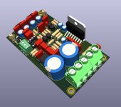
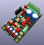
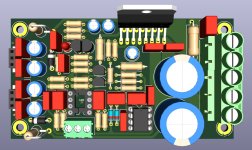
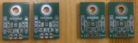
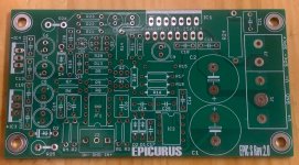
Finally, EPIC S Rev2.0 is ready. All details have been updated in post #1. The PCBs have been sent for production. Happy DIY!
Attachments
-
 FF916CD6-F51F-42D0-9DE7-8423955D5FC4.png326.2 KB · Views: 194
 -
 19D2023D-E48A-47BA-9A25-7174A4204F04.jpeg296.1 KB · Views: 179
 -
 7942FC7A-52B6-4A83-8686-7F9D640BC0DF.jpeg327.9 KB · Views: 129
 -
 C4F0F39E-B0C3-44B2-AFDC-9D5D8DC8D2BE.jpeg504 KB · Views: 126
 -
 C73FC9B5-7A2D-4CE7-B468-8262CD528128.png993.9 KB · Views: 178
Final prototype measurement of Epic S.
1K-1NF input filter
47K-4.7K NFB Resistors
4.7mA Input bias

1K-1NF input filter
47K-4.7K NFB Resistors
4.7mA Input bias
Years ago I made a famous LM3886 for my friend. After designing the Epic S, I asked him to compare the two amplifiers. He said he would continue with the EPIC S and completed the assembly.
Attachments
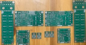
PCB Available…
I have prepared BOM for all PCB.
EPIC S has two kinds of BOM. One of with CMF series resistors, another is standard metal film resistors.
Enjoy.
I have prepared BOM for all PCB.
EPIC S has two kinds of BOM. One of with CMF series resistors, another is standard metal film resistors.
Enjoy.
Attachments
-
 EA45BDBA-D684-4353-ACAD-3748AD6B0ADD.jpeg680.1 KB · Views: 104
 -
 D520800E-56CB-490F-928E-3C107DF13A6C.jpeg829.8 KB · Views: 98
 -
 18A78857-C672-42C3-809B-2C6A7AA411FA.jpeg371.3 KB · Views: 84
 -
 57078CFF-1776-4443-B112-7B3D88800B8E.jpeg460.5 KB · Views: 93
 -
 C52911C7-4F72-4F8B-AA9D-ED8D7B17C6AB.jpeg666.5 KB · Views: 104


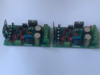
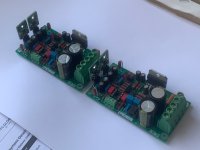
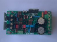
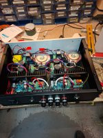
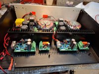
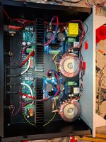
EPIC S amplifier.
Attachments
-
 D639E46D-D9A2-43C3-87A3-C60C5CE349BB.jpeg554.4 KB · Views: 73
 -
 5AE1D19D-1EBF-4455-BBD1-338861B8168A.jpeg433.8 KB · Views: 71
 -
 ABB3176C-DF8E-4B0E-9430-B0F61E7A08FB.jpeg569.4 KB · Views: 79
 -
 8A511C4E-568C-416A-9FD3-C6CA8967C968.jpeg658.6 KB · Views: 71
 -
 ECF8E610-BA36-4FCB-8087-82CE5A6C3388.jpeg280.9 KB · Views: 71
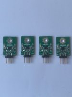
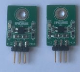
This class A input buffer did a great job with the tda7293 in my opinion. I can say that it works well especially for someone like me who uses nos dac and alps potentiometer. After all, you haven't listened to this amp. I wish you had the chance to listen to it.
- Home
- Amplifiers
- Chip Amps
- TDA7293+JFE2140(LSK489)composite feedback amplifier