Hi!
Now I see.
That's the learning curve. For each problem resolved, there is a step up in learning 🙂
These pins perform the DC offset for when you are amplifying DC signals, so you need precision on DC levels such as thermocouple, pressure sensors etc.
For this audio aplication, where we simply strip off DC by using capacitor at the input and output there is no need for precise offset adjustments.
In terms of TL081, +V is pin 7 so goes to +VCC and -V is pin 4 so goes to ground.
In my protobord actual picture, I used the TL072, which has a different pinout, since it is a dual opamp.
See the schematic with pins for TL081.
Pin 2: -IN
Pin 3: +IN
Pin 4: -VCC (goes to GND)
Pin 6: Output
Pin 7: +VCC

Now I see.
That's the learning curve. For each problem resolved, there is a step up in learning 🙂
You don't need to connect these pins N1 and N2. Just leave them disconnected (floating).So, in the datasheet for the TL081, they call the "Input offset adjustment" pins "offset N1" & "offset N2"
These pins perform the DC offset for when you are amplifying DC signals, so you need precision on DC levels such as thermocouple, pressure sensors etc.
For this audio aplication, where we simply strip off DC by using capacitor at the input and output there is no need for precise offset adjustments.
Yes, just a short. This creates the unity gain. When you need more gain, then you use 2 resistors, one from output to the -IN and another from the -IN to ground.Also, is it really a dead short between out and -? No resistor there?
No, I meant +V to VCC and -V to ground.In your schematics for example, if i read it correctly, Offset N1 (Pin1) should be directly shorted to ground, and Offset N2(Pin 5) directly shorted to V+?
In terms of TL081, +V is pin 7 so goes to +VCC and -V is pin 4 so goes to ground.
In my protobord actual picture, I used the TL072, which has a different pinout, since it is a dual opamp.
See the schematic with pins for TL081.
Pin 2: -IN
Pin 3: +IN
Pin 4: -VCC (goes to GND)
Pin 6: Output
Pin 7: +VCC
Hello!
Thank you so much again for bearing with me on this endeavor 😂
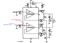
No wonder I got some strange results then. Because I followed the logic symbol in the datasheet and tried to translate it over to circuit, like this:

Here these ”offset” pins are marked where the vcc +/- is on the schematic.
Haha pretty funny. Surprised that nothing fried and that I got somewhat of a signal out.
Tomorrow I attempt another rebuild, hopefully this time around I’ll get it right! 😂😂😂
Will post some measures to see where we are after that!
Again, thanks for all assistance!
Thank you so much again for bearing with me on this endeavor 😂
No wonder I got some strange results then. Because I followed the logic symbol in the datasheet and tried to translate it over to circuit, like this:
Here these ”offset” pins are marked where the vcc +/- is on the schematic.
Haha pretty funny. Surprised that nothing fried and that I got somewhat of a signal out.
Tomorrow I attempt another rebuild, hopefully this time around I’ll get it right! 😂😂😂
Will post some measures to see where we are after that!
Again, thanks for all assistance!
Ok! One step a time and you'll get there.
Just for curiosity, if you look at the TL081 datasheet, this is how to use the offset pins.
You adjust the trimpot and get the offset adjuted.

Just for curiosity, if you look at the TL081 datasheet, this is how to use the offset pins.
You adjust the trimpot and get the offset adjuted.

Hello!
Now! Finally I think we have at least the op-amp sorted.
Re-did everything with the new info you gave me, and it seems to work pretty well.
Please check out the screenshots. (Note, still not hooked up this to the TDA just yet, cliffhanger 😀)
However, the only thing I noticed is that it starts to clip just below 400mv, that is about 2-3 clicks away from full volume on the player.
This does not happen on the player, just on the op-amp output. The load is 10Kohm, is this expected or might it be something else?
I'm still using the chip that I had incorrectly hooked up, so its entirely possible that it might be fried if this is not expected.

FFT:

Now! Finally I think we have at least the op-amp sorted.
Re-did everything with the new info you gave me, and it seems to work pretty well.
Please check out the screenshots. (Note, still not hooked up this to the TDA just yet, cliffhanger 😀)
However, the only thing I noticed is that it starts to clip just below 400mv, that is about 2-3 clicks away from full volume on the player.
This does not happen on the player, just on the op-amp output. The load is 10Kohm, is this expected or might it be something else?
I'm still using the chip that I had incorrectly hooked up, so its entirely possible that it might be fried if this is not expected.
FFT:
Hello!
Good news! And no 2nd harmonic!
Regarding the clipping, by removing the AC signal, check if DC levels at the +IN (pin 3) and output (pin 6) is around 50% of the +V.
If it doesn't have this DC levels, check the connections, and resistors.
But if there is around 50% at these points and still the opamp clips, the opamp is probably gone.
This circuit should "copy" exactly what is in the +IN (pin 3). Max peak should go a bit lower than 50% of the +V.
Example: if +V is 20V, DC level should be 10V and sinewave should be able to swing from around -8V to +8V after the 100uF capacitor (how much close to the power supply or ground depends on the opamp).
If you measure right in the output pin 6, the signal can swing from 2V to 18V in case of +V is 20V.
It will always be limited by the power supply minus some voltage loss that is due to the internal opamp transistors.
Alright!
I did a pickup/replace resistors and now clipping are gone. So most likely some bad connection within the breadboard.
Surprising, thought the IC was toast as I think it has been through a lot. 😂
But now it looks great and will prepare to hook this up to the main TDA circuit and see if we finally get that 2nd harmonic do be gone!
Meanwhile, I’m a bit curious, when calculating the THD %, how is that done for a trace like this?
I can add a THD measure on the scope, which shows me around 0,39x% THD. But don’t know if this calculation is the best or if it should be done in some other way?
When adding that measurement, I can adjust some parameters like number of bins and so on, which affects the THD indicated by alot, so that seem a little confusing.
Cool!! Dominating the opamp is very handy for infinite applications.
Regarding THD, let's take the Wikipedia formula to facilitate:

If you consider only one harmonic it will be simply THD = Vharmonic/Vfundamental multiplied by 100 to get in percentage
If using the oscilloscope spectrum analysis, you get the values in dB and you'll need to convert to voltages.
If the harmonic is 40dB below the fundamental, it means 1% THD.
dB = 20 log(Vharmonic/Vfundamental) or
Vharmonic/Vfundamental=10^(dB/20)
Vharmonic/Vfundamental=10^(-40/20)=10^(-2)=0.01, which is 1%
For calculating THD with more than one harmonic, you need to convert dB to volts and use the formula above from Wiki.
Just use fundamental as reference and derive the harmonics based on that value - the absolute value of fundamental in volts is not much important, since the formula will focus on the relation between the fundamental and the harminics. E.g.: 1V fundamental and 0.1V harmonic = 10%. But if fundamental is 10V and harmonic is 1V the result is the same.
Here's a detailed video explaining the process:
For measuring things below 48dB, you can use the sound card of a PC which is based on 16-bit and can measure very low levels of THD down to 0.0015% theoretically. But, keep in mind that measuring so small THD needs a very low noise circuit and environment - not very easy to achieve.
To practice and validade, you can do what you did in the very begining: prepare sine waves with know distortion levels and take the measurements. Compare and see if the measurements are consistent.
Regarding THD, let's take the Wikipedia formula to facilitate:
If you consider only one harmonic it will be simply THD = Vharmonic/Vfundamental multiplied by 100 to get in percentage
If using the oscilloscope spectrum analysis, you get the values in dB and you'll need to convert to voltages.
If the harmonic is 40dB below the fundamental, it means 1% THD.
dB = 20 log(Vharmonic/Vfundamental) or
Vharmonic/Vfundamental=10^(dB/20)
Vharmonic/Vfundamental=10^(-40/20)=10^(-2)=0.01, which is 1%
For calculating THD with more than one harmonic, you need to convert dB to volts and use the formula above from Wiki.
Just use fundamental as reference and derive the harmonics based on that value - the absolute value of fundamental in volts is not much important, since the formula will focus on the relation between the fundamental and the harminics. E.g.: 1V fundamental and 0.1V harmonic = 10%. But if fundamental is 10V and harmonic is 1V the result is the same.
Here's a detailed video explaining the process:
Here you need to know what are the limitations of your scope. An 8-bit scope will be limited to measure down to -48dB only or 0.39%.I can add a THD measure on the scope, which shows me around 0,39x% THD. But don’t know if this calculation is the best or if it should be done in some other way?
When adding that measurement, I can adjust some parameters like number of bins and so on, which affects the THD indicated by alot, so that seem a little confusing.
For measuring things below 48dB, you can use the sound card of a PC which is based on 16-bit and can measure very low levels of THD down to 0.0015% theoretically. But, keep in mind that measuring so small THD needs a very low noise circuit and environment - not very easy to achieve.
To practice and validade, you can do what you did in the very begining: prepare sine waves with know distortion levels and take the measurements. Compare and see if the measurements are consistent.
That level of noise / THD is good enough to listen to music at home at normal volumes.
The 2004 is a car radio chip amp, sound quality may not be as good as 1875 / 2030 series chip amps intended for home use.
The 2004 is a car radio chip amp, sound quality may not be as good as 1875 / 2030 series chip amps intended for home use.
Thanks for the measuring insights! ⭐
Alright! So I have now hooked up the op-amp circut to the TDA, and .. Yes, the 2nd harmonic is still clearly there. Its like set in stone.
I had high hopes for the op-amp as it felt reasonable that this chip loaded the lil' mp3 player maybe to much and needed some buffering, but no.
There is virtually no difference with the 2nd harmonic on the output of the TDA.
That is the red thread here, no matter what I do to it, that circuit is extremely stable with this 2nd harmonic.
What are we up against? Is this just expected from the TDA2004R in bridge mode? Or is there some cap in my board not up to spec? They are all new, genuine and with the same values as in the data sheet example though. Resistor some where? I used metal film for every one though.
EDIT:
I should add that it does seem like it is not "spilling" this back out to the input/output of opamp, as it did with the straight from MP3-player though. Now input looks clean
Last edited:
Hello!
This is not an easy one!
But at least, the environment is more controlled now.
The 2nd harmonic is being generated by the TDA, since now the input signal, which correspond to the output signal of the opamp, is clean as you observe.
Have you measured the TDA in single ended? Just connect the scope to ground and measure each TDA output using scope DC decouple mode.
Just to check again if the bridge mode is causing this distortion or if in single ended mode the 2nd harmonic is also present.
I remember in the first posts, you've made this measurement and confirmed in single ended the 2nd harmonic was there, but now we know that the 2nd harmonic at that time was also present in the TDA input. Now we have a different situation.
I mention this cause in theory, for measuring a bridge mode amp we should have a differential probe or a differential pre-amp to convert the non grounded reference to a grounded reference signal. Remember that in bridge mode none of the output leads is ground. So when you connect the scope ground in one of the leads it is not exactly what we should do. If there is no 2nd harmonic in single ended, then, maybe, a better method of measuring bridge mode must be performed. See suggestion below, if this is the case.
Now that you can play with opamps, you can build a simple differential amplifier for measuring a non grounded bridge mode amp output.
I've tested the circuit below when I wanted to measure a class-D bridge amp, which requires a high frequency filter for eliminating ultrasonic frequencies.
You can use a simplified version for class-AB, which doesn't have the high frequency noise of class-D amps. See further below.
The output will be 10 times lower than the amp signal, since there is an attenuation for protecting the opamp input in case of high power amps.
If you set your amp to output 4Vpeak, you'll see 400mVpeak. It's just a matter of adjusting scope scale.
You can also play with feedback resistors to put a gain, restoring original amplitude - opamps are very flexible tools.
These circuits use symetrical power supply (+V, GND and -V) to make things easier.
For single +V, we have to adapt them.
Last edited:
Check with a 12V battery, or a 4 x 3.7V battery, to rule out supply issues.
2004 should tolerate that kind of voltage.
2004 should tolerate that kind of voltage.
Hello!
Yes, it seem to be really really tricky. I'm very impressed by your patience and even mine too with this 😀
I can confirm that the distortion is still there in single ended.
Now I did find some interesting stuff while just measuring just about everywhere, I'm not sure if they are important and might help us but here goes: (essentially I was just poking around in desperation 😀)
I have op-amp on separate breadboard.
Measuring this while its connected to the TDA, the distortion is gone.
But! If i keep the ground lead of my scope on the TDA-board, while measuring output of op-amp, the 2nd harmonic shows up even on input.
So, Its gone if I ground my scope close to the op-amp instead. Do note that both boards are connected to the same grounds and power supply, just separated physically.
I did also discover something else that is very interesting, probably the most interesting yet. (I think). While in bridge mode, the second input of the amp is grounded through a 2.2uF cap.
Now If i measure this pin (#5), I get the 2nd harmonic there. But get this, just the 2nd harmonic, nothing else. Its not as "high" as the other, but its clearly there. What can this indicate? Or is this "obvious" when we have the problem I have?
But I guess now that since we do still see this distortion in single ended, there is no need for it?
Thank you so much for posting these ideas though, I think I will consider to build them in the future!
Yes, it seem to be really really tricky. I'm very impressed by your patience and even mine too with this 😀
I can confirm that the distortion is still there in single ended.
Now I did find some interesting stuff while just measuring just about everywhere, I'm not sure if they are important and might help us but here goes: (essentially I was just poking around in desperation 😀)
I have op-amp on separate breadboard.
Measuring this while its connected to the TDA, the distortion is gone.
But! If i keep the ground lead of my scope on the TDA-board, while measuring output of op-amp, the 2nd harmonic shows up even on input.
So, Its gone if I ground my scope close to the op-amp instead. Do note that both boards are connected to the same grounds and power supply, just separated physically.
I did also discover something else that is very interesting, probably the most interesting yet. (I think). While in bridge mode, the second input of the amp is grounded through a 2.2uF cap.
Now If i measure this pin (#5), I get the 2nd harmonic there. But get this, just the 2nd harmonic, nothing else. Its not as "high" as the other, but its clearly there. What can this indicate? Or is this "obvious" when we have the problem I have?
Building these differential probe circuits would be a very nice thing, I would even consider etching a board to keep it on, since its a good tool to have in the future.I mention this cause in theory, for measuring a bridge mode amp we should have a differential probe or a differential pre-amp to convert the non grounded reference to a grounded reference signal. Remember that in bridge mode none of the output leads is ground. So when you connect the scope ground in one of the leads it is not exactly what we should do. If there is no 2nd harmonic in single ended, then, maybe, a better method of measuring bridge mode must be performed. See suggestion below, if this is the case.
But I guess now that since we do still see this distortion in single ended, there is no need for it?
Thank you so much for posting these ideas though, I think I will consider to build them in the future!
Last edited:
Hi! No worries - I'm having fun and I'm learning with you. I love analog audio circuits.Yes, it seem to be really really tricky. I'm very impressed by your patience and even mine too with this 😀
But the toolbox is getting empty 🙂
Yes, you can focus in one single amp (the upper amp) to try to solve the problem. It's a small circuit to focus on.But I guess now that since we do still see this distortion in single ended, there is no need for it?
It might indicate ground issues.Now If i measure this pin (#5), I get the 2nd harmonic there. But get this, just the 2nd harmonic, nothing else. Its not as "high" as the other, but its clearly there. What can this indicate? Or is this "obvious" when we have the problem I have?
In the ideal world, the GND would have zero volt in any point - at the power supply, at the input ground, output ground etc.
But in real world, we know that this is not the case. Every single wire or PCB track is a composition of resistance, capacitance and inductance.
This can generate voltages due to current flow, it can capture electromagnetic induction etc.
You see, probing the pin 5 with the scope, you should see 0 volt not any 2nd harmonic there.
This proves that GND has not same voltage across all points - I'm talking about mili or micro volts, of course.
Never trust GND is the "same" even if it looks all physically connected together.
Some checks:
1) Probe pin 5 and find the 2nd harmonic. Move the scope to the GND connection where the 2.2uF capacitor is connected to, do you see this 2nd harmonic?
Is this capacitor good? If ground doesn't have the harmonic, try to connect another capacitor in parallel - try a bigger one and also a film capacitor.
2) When you measured the single ended, did you measure the pin 10?
3) Things I'd try is to move GND points to feed the PCB, to connect the scope, to connect the audio source etc.
I don't have much more ideas up until now.
Attachments
One thing more, I'd try is to separate these 2 amps to work just with the upper one - the one that receives the audio input.
I don't like the way this circuit inverts the signal, by taking the output of the upper amp and injecting it in the bottom amp.
I would invert the signal by using an opamp and feeding the bottom amp with the inverted signal.
The separation is easy: remove R4.
In order to focus on testing the upper amp, connect the speaker through a 1000uF (or bigger) to the amp output and to the ground.
The capacitor is needed since now you'll have a DC component at the amp output.
Hey!
I'm back after getting some inspiration. Needed to put it away for a while 😀
So, first of all. I tried with a battery. The exact same issue still present. No change there. So i think the PSU can finally be put to rest as a suspect.
Further:
1: Yes, unfortunately I noticed that the 2nd harmonic is in the ground after probing around some more.
2: Yep, same present there
3: I have moved around GND feed and even added more. The only time I even got the 2nd harmonic to move in either direction, was to add a separate clamp all the way from input power source, to the GND pin itself on the chip. It lowered the harmonic from -33,9 down to 40,0.
I do suspect though, that this is more hiding the problem than the problem itself, is that a fair assumption?
Also further, I did try the suggested way to remove R4 and add a 1000uF and then speaker directly to ground.
Interesting thing is that the 2nd harmonic seem to dissapear then. However, the scope view is looking extremely fuzzy.
It does also furthermore seem to put the amp in some form of unknown state, where it slowly just starts to ramps up power consumption, seemingly without adding any real power to the output. So, not sure why that is happening?
Please see the screenshots of that views:
(Please ignore the small view of the FFT in scopeview, i messed up the screenshots for some reason)
Hi!So, first of all. I tried with a battery. The exact same issue still present. No change there. So i think the PSU can finally be put to rest as a suspect.
Good, so it doesn't come thru power supply.
If you see the 2nd harmonic on GND itself, you jump a GND directly to the TDA GND pin and 2nd harmonic changes, it indicates layout issues and thus, indicating that changes on layout would minimize or eliminate this problem. There is 2nd harmonic current flowing in the GND area. You can try to keep this layout (in order to not throw away this PCB) and just run additional GND from/to specific points in the PCB as you did as a test. If you find a good result, just make the changes permanent.1: Yes, unfortunately I noticed that the 2nd harmonic is in the ground after probing around some more.
2: Yep, same present there
3: I have moved around GND feed and even added more. The only time I even got the 2nd harmonic to move in either direction, was to add a separate clamp all the way from input power source, to the GND pin itself on the chip. It lowered the harmonic from -33,9 down to 40,0.
I do suspect though, that this is more hiding the problem than the problem itself, is that a fair assumption?
Here we have interesting information. No brigde, no 2nd harmonic. The fuzzy behavior is just oscillation, which also causes the higher current consumption.Also further, I did try the suggested way to remove R4 and add a 1000uF and then speaker directly to ground.
Interesting thing is that the 2nd harmonic seem to dissapear then. However, the scope view is looking extremely fuzzy.
It does also furthermore seem to put the amp in some form of unknown state, where it slowly just starts to ramps up power consumption, seemingly without adding any real power to the output. So, not sure why that is happening?
Using additional 100nF capacitors here and there (or modifying current values), you can get rid of this oscillation. Just make sure the oscillation doesn't come from the other amp that was deactivated since its circuit got not unconfigured. Also check the GND different points and also the +V if they are no oscillating.
During these tests, caution must be taken since when oscillating it might drain too much current and IC might blow.
Two paths to follow if I were you:
1) It seams to be more a layout issue. Since it is difficult to understand where the current is flowing, where all the spurious inductances and capacitances are, the only way to resolve this is by trial and error. Maybe another layout is needed or, as I said, run external wires over the current PCB, feeding the PCB by different sides (power, input and output), adding more decoupling capactors here and there etc. This is how I resolved many PCB with similar issues I've built. I know it's not a "scientific way" of resolving these issues but it's beyond my knowledge. In addition, I prefer the star GND layout, where we can better understand where the current is flowing since all the GND are sourced from a single point. Many PCB's I've built this way worked right away without any trick.
2) I don't like the way this bridge mode was created, by using the output of one amplifier to feed the input of the other. This might also be causing the problem, since you've confirmed that the single ended version works fine, except the oscillation, without the 2nd harmonic. You can try this path by trying to remove the oscillation and get a clean single ended amp. Then, I'd make the other amp to work clean as a single ended with the same configuration of the other amp. Finally, I'd add an external opamp with unitary gain just inverting the signal for one of the amps. Then I'd restore the bridge mode, but this time, with each amp being independent.
Regards!
Hello,
And as usual, thanks a lot for your patience and sharing your wealth of knowledge about this.
I think we just had a major breakthrough in the troubleshooting of this!
I'm pretty sure that after we added the op-amp to the circuit, we fixed one problem but added another, that in the end showed up as the same issue.
Here goes:
After adding, removing and even changing out components, the 2nd harmonic was still there, and it has always been suuuper stable, no matter how much i handle the board, or even touch the components, it was just there.
As you saw earlier I manage to lower the 2nd ever so little by adding separate ground to the board. However, it did not matter where i put it on the board.
And it was not possible to lower it more than this, no matter what i did to it.
Now when all else failed I had the idea to make GND jump from the op-amp ground(breadboard), to the board ground.
They previously was on the same lead, but, i guess the lab-cable introduced issues.
Now, by just touching a jumper wire as ground between op-amp ground and the ground-plane, the 2nd harmonic almost, disappear. I say almost disappear, because, we can still see a spike there, however, its around the other noise. (This is just me touching with the jumper, not even soldered in place, so might still improve more)
So if I'm not fooling myself, I think the measurement looks very much improved? Note, this measurement is pretty high amplitude, almost maxed out.
Before, the 2nd harmonic would be very very high at this amplitude.

Now, to just confirm that this really was not the original problem, I reverted back to feeding the amp signal via the original input, and then attempted to add a ground wire from input jack all the way to the amp itself, but the original problem was still there.
This leads me to think that we fixed the original problem(amp loading the mp3player in some way to make the 2nd harmonic happen), but got another one with the op-amp due to the poor grounding of that separate circuit in relation to the PCB?
And as usual, thanks a lot for your patience and sharing your wealth of knowledge about this.
I think we just had a major breakthrough in the troubleshooting of this!
I'm pretty sure that after we added the op-amp to the circuit, we fixed one problem but added another, that in the end showed up as the same issue.
Here goes:
After adding, removing and even changing out components, the 2nd harmonic was still there, and it has always been suuuper stable, no matter how much i handle the board, or even touch the components, it was just there.
As you saw earlier I manage to lower the 2nd ever so little by adding separate ground to the board. However, it did not matter where i put it on the board.
And it was not possible to lower it more than this, no matter what i did to it.
Now when all else failed I had the idea to make GND jump from the op-amp ground(breadboard), to the board ground.
They previously was on the same lead, but, i guess the lab-cable introduced issues.
Now, by just touching a jumper wire as ground between op-amp ground and the ground-plane, the 2nd harmonic almost, disappear. I say almost disappear, because, we can still see a spike there, however, its around the other noise. (This is just me touching with the jumper, not even soldered in place, so might still improve more)
So if I'm not fooling myself, I think the measurement looks very much improved? Note, this measurement is pretty high amplitude, almost maxed out.
Before, the 2nd harmonic would be very very high at this amplitude.
Now, to just confirm that this really was not the original problem, I reverted back to feeding the amp signal via the original input, and then attempted to add a ground wire from input jack all the way to the amp itself, but the original problem was still there.
This leads me to think that we fixed the original problem(amp loading the mp3player in some way to make the 2nd harmonic happen), but got another one with the op-amp due to the poor grounding of that separate circuit in relation to the PCB?
Hi!
If you scope is based on 8 bits, the FFT shows harmonics and noise at levels betwee -45dB and -50dB more or less, which is the limit of this type of scope and this would indicate that there is no 2nd harmonic problem in that scenario. So amp is clean. In addition, the manufacture doesn't promisse much better than that, since datahseet THD goes from typical 0.2% (-53dB) to max 1% (-40dB).
With the GND tests you have performed, it seams we have layout problems, mainly the GND layout.
When you jump GND point 1 to GND point 2 and distortion changes, it means there is some undesirable current flowing in the GND tracks creating voltages along the tracks - the wire diverts current from one path to another. Remember ideally GND should have 0 volt in any point.
But we know in the real world this is not true.
I really don't have any other idea but playing with the GND layout and try to find a scenario that works fine on the current PCB or build another PCB layout.
If moving to a new PCB, I'd try a start topology - not sure if it's going to work, since I'm not a speciallist in PCB.
You can even try this star topology idea in a protoboard.
You can even transform your current PCB in a star topology by interrupting some GND and bring a new GND from a single GND point through external wires to the destination. See below just an idea of central GND. This is not a layout suggestion, but just a picture to discuss the idea.
There you can see that the current flowing on each GND track has only one destination so no shared currents.

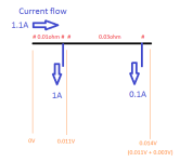
See the example below. There are 2 current flows sharing the same wire.
Assuming 0V on the far left, you get 2 non zero voltages along the wire since it has some resistance (0.01ohms + 0.03ohms).
Note that if each current flow changes, all voltages will change.
This is the problem with sharing a single track for multiple currents.
In audio scenario, imagine if the first 1A load is the rectifier GND and current has a ripple of 120Hz.
If 0.1A wire point is a reference GND for a small signal part of the amplifier, noise of 120Hz will be present, cause the amp expects that GND is 0V but it isn't.
And note that this is a simplified analysis considering just the wire resistance.
In real world the wire is a composition of resistance, inductance and capacitance, all non-linearly distributed along the wire - things go insanely complex to model or understand.
That's why, in my case, I rely on trial and error and experience to resolve these issues. Star topology really helps cause you isolate problems.

If you scope is based on 8 bits, the FFT shows harmonics and noise at levels betwee -45dB and -50dB more or less, which is the limit of this type of scope and this would indicate that there is no 2nd harmonic problem in that scenario. So amp is clean. In addition, the manufacture doesn't promisse much better than that, since datahseet THD goes from typical 0.2% (-53dB) to max 1% (-40dB).
With the GND tests you have performed, it seams we have layout problems, mainly the GND layout.
When you jump GND point 1 to GND point 2 and distortion changes, it means there is some undesirable current flowing in the GND tracks creating voltages along the tracks - the wire diverts current from one path to another. Remember ideally GND should have 0 volt in any point.
But we know in the real world this is not true.
I really don't have any other idea but playing with the GND layout and try to find a scenario that works fine on the current PCB or build another PCB layout.
If moving to a new PCB, I'd try a start topology - not sure if it's going to work, since I'm not a speciallist in PCB.
You can even try this star topology idea in a protoboard.
You can even transform your current PCB in a star topology by interrupting some GND and bring a new GND from a single GND point through external wires to the destination. See below just an idea of central GND. This is not a layout suggestion, but just a picture to discuss the idea.
There you can see that the current flowing on each GND track has only one destination so no shared currents.
See the example below. There are 2 current flows sharing the same wire.
Assuming 0V on the far left, you get 2 non zero voltages along the wire since it has some resistance (0.01ohms + 0.03ohms).
Note that if each current flow changes, all voltages will change.
This is the problem with sharing a single track for multiple currents.
In audio scenario, imagine if the first 1A load is the rectifier GND and current has a ripple of 120Hz.
If 0.1A wire point is a reference GND for a small signal part of the amplifier, noise of 120Hz will be present, cause the amp expects that GND is 0V but it isn't.
And note that this is a simplified analysis considering just the wire resistance.
In real world the wire is a composition of resistance, inductance and capacitance, all non-linearly distributed along the wire - things go insanely complex to model or understand.
That's why, in my case, I rely on trial and error and experience to resolve these issues. Star topology really helps cause you isolate problems.
Attachments
Hello!
Great then the measurement looks good now, then we are on the right track!!
Yep it’s a 8-bit scope
Yes, so, maybe my last message was not too clear of what I meant. 😅
So, currently we have the op-amp setup on a breadboard at the side. Which in turn is connected to the PSU via jumper wires, both power and ground.
Further, we have the audio connections from it to the PCB signal input.
Then we have my PCB with the TDA on it, it is also connected to the PSU at the same point.
What was done to get the 2nd harmonic to go away, was to just connect my breadboards ground point directly to the ground plane on the PCB, instead of going around via the lab-cables at the PSU. This instantly removed the 2nd harmonic. This to me, points more to just a bad GND connection between the breadboard and the PCB, rather than bad ground plane layout at the PCB end?
To try and confirm if this was the issue all along, even with the player signal ground, I removed our op-amp and tried to feed that ground as close to the amp chip ground as possible, but then the error showed up as before. This is why I think we had two separate issues, one before creating the op-amp and one after.
1. First (without op-amp) we where, as you thought earlier in the thread, loading the mp3player in such a way the 2nd harmonic showed up.
2. After creating the op-amp we had instead bad GND layout when I hooked the breadboard up to the main PCB, which is most likely true as flimsy jumper wires to a breadboard is always a issue, I think.
So, I think I can keep about the same layout, but add the op-amp to the circuit, of course I will need to make a new PCB. But that is no issue, as long as we can be fairly certain this was in fact the issue.
Does this make sense? 😀
Ah ok! Cool! It is really better to centralize the GND as much as possible, specially for the small signal path. So attach the opamp as close as possible to TDA GND and keep just this GND as ground for the opamp.What was done to get the 2nd harmonic to go away, was to just connect my breadboards ground point directly to the ground plane on the PCB, instead of going around via the lab-cables at the PSU. This instantly removed the 2nd harmonic. This to me, points more to just a bad GND connection between the breadboard and the PCB, rather than bad ground plane layout at the PCB end?
Sure, I'd keep as much as possible what is already built such as the TDA PCB. If you found a layout that works, just use it. In this case a small additional PCB for the opamp connected the same way you did when in breadboard, specially the GND.So, I think I can keep about the same layout, but add the op-amp to the circuit, of course I will need to make a new PCB. But that is no issue, as long as we can be fairly certain this was in fact the issue.
Just note that when this opamp PCB is ready, lots of other changes will happen - let's hope these changes don't affect the final result.
But again, if it happens, try different GND, power, signal connections etc.
Now you have more experience with these tricks.
Good luck!
- Home
- Amplifiers
- Chip Amps
- TDA2004 Bridge configuration, distortion/2nd harmonic?