THLAudio finally came through, took almost two months start to finish though. Oy. So now my board is complete, just have to verify the voltages tomorrow and it will basically be good to go.
So is there anyone else out there besides me who probably isn't going to use a toroidal transformer for this DAC? For one thing since I'm putting this in a case with a CD transport the physical size of such a beast somewhat of a detriment. I've also read plenty about split bobbins and r-cores being better for digital anyways.
Any thoughts?
Strohmie said:THLAudio finally came through, took almost two months start to finish though. Oy. So now my board is complete, just have to verify the voltages tomorrow and it will basically be good to go.
So is there anyone else out there besides me who probably isn't going to use a toroidal transformer for this DAC? For one thing since I'm putting this in a case with a CD transport the physical size of such a beast somewhat of a detriment. I've also read plenty about split bobbins and r-cores being better for digital anyways.
Any thoughts?
Well I'm using a pair of split bobbin transformers for the digital parts, an E/I core for the analogue supply for the dac chip and a 80vA toroidal for the output stage, these are basically all I could find locally so I'll use them for now.
I would like a single R-core with all the needed secondary's though🙂
Caddock resistors are ordered, I'm still struggling with the 0.1uf Wima MKP10's though
Let us know what you think of the dac, I'm sure you will be happy😉
And the lord said to rise up-ah...
I *still* haven't been able to fire this baby up yet. Been building a CD player and am integrating the DAC, but I'm missing a couple parts before it'll be all done.
So, anyone with any opinions/tweaks/warnings/hi-fi-goodness?
I *still* haven't been able to fire this baby up yet. Been building a CD player and am integrating the DAC, but I'm missing a couple parts before it'll be all done.
So, anyone with any opinions/tweaks/warnings/hi-fi-goodness?
printec circuit boards for dac
Hello,
I am coming rather late to this thread. I would like to know if there are any boards left... I will need to build a good dac soon, to complement my CD PRO project.
gilid
Hello,
I am coming rather late to this thread. I would like to know if there are any boards left... I will need to build a good dac soon, to complement my CD PRO project.
gilid
Mines been up and running for a few weeks now, the sound keeps improving as the Blackgates burn in.
I'm very pleased with it😉
All I need is a nice case and possibly a single transformer with all the needed secondarys would be good.
I compared the Rikens against the Caddock TFO20 for the 1k5, although the Caddocks was harder to fit I prefer these over the Rikens
I'm very pleased with it😉
All I need is a nice case and possibly a single transformer with all the needed secondarys would be good.
I compared the Rikens against the Caddock TFO20 for the 1k5, although the Caddocks was harder to fit I prefer these over the Rikens
So close, yet so far.
Alright. Testing everything out. +/-5 on the TDA1541A look good. +/-12 on the AD844 look good (though I think I may have fried one of them when I accidentally connected two of the pins. Ugh.). Now for the problem -- I'm getting -17.53V at the analog pin of the 1541A. Now, I'm using a 24VAC toroid for this part, which is higher than the recommended 21-22VAC, but the regulator should drop any voltage I give it to 24V (and I am going to have to heatsink here, methinks). So that shouldn't be the problem. Now, my assumption with the TL431 circuit is that it's designed to drop the remaining ~9V to get it to -15V. I've checked the resistors to make sure their value gels with the original design -- mine are 5k11, 1k, and 221, which corresponds to the 5k1, 1k, and 220 in the design. Should be right. No puffy caps, and the TL431 looks to be in the correct orientation. It does at least appear to be dropping 5.5V, but not 9V.
So what's accounting for the 2.5V I'm missing? I have the TDA1541A in there right now, so it isn't as if the pin isn't being loaded (unless an analog signal needs to be flowing for the remaining voltage drop, but I don't know about that -- I can already tell the 1541A is pulling current because the 24V reg is heating up).
Hypothetically this (and possibly the accidentally blown AD844) are the last pieces before everything should be done. Any help would be appreciated.
I recall I had a similar problem with obtaining proper voltage on analog supply pin. In my case the ground connections (D & A) were at fault (or actually missing).
If this is not the case, you might try to increas series resistor to the TL431, although I don't think this a problem here.
If this is not the case, you might try to increas series resistor to the TL431, although I don't think this a problem here.
What did you do to ground the board? I've never been entirely clear on how to ground the two planes separately -- I have th digital ground corresponding to the same digital ground on my transport by connecting the ground pin from the I2S connection, but the analog ground probably isn't well accounted for. Just to check, I connected the analog and digital grounds, thus giving them the same ground reference, and that didn't change the voltage on that pin.
On the boards from Thomas, digital and analog grounds are separated, and IIRC they connect through analog stage and analog and digital PS. In case of using a sepparate analog supply, I was missing ground connection. Correctly, both grounds should be conected directly at the chip, and this is how I did it later.
Might have found my problem...
Could anyone out there give me the impedance reading between the ref and out pins on their TL431 in that -15V supply? I'm thinking mine might be fried, because I'm getting a total impedance, including the 5k1 resistor and TL431, of only about 35 ohms.
Could anyone out there give me the impedance reading between the ref and out pins on their TL431 in that -15V supply? I'm thinking mine might be fried, because I'm getting a total impedance, including the 5k1 resistor and TL431, of only about 35 ohms.
check this ...
TDA1541A rev1.1b DAC reclocker info :
http://users.verat.net/~pedjarogic/audio/tda1541a_dac/tda1541a_dac_rev.htm#reclocker
http://users.verat.net/~pedjarogic/audio/tda1541a_dac/tda1541a_dac_rev_meas2.htm
Boban
TDA1541A rev1.1b DAC reclocker info :
http://users.verat.net/~pedjarogic/audio/tda1541a_dac/tda1541a_dac_rev.htm#reclocker
http://users.verat.net/~pedjarogic/audio/tda1541a_dac/tda1541a_dac_rev_meas2.htm
Boban
Custom Trafo Available.......
Hi All,
I am putting together a GP for a custom-wound trafo for Pedja's DAC.
Details here: http://www.diyaudio.com/forums/showthread.php?s=&threadid=42003
WIKI here: http://www.diyaudio.com/wiki/index.php?page=Antrim+Trafo
Cheers
Jon
Hi All,
I am putting together a GP for a custom-wound trafo for Pedja's DAC.
Details here: http://www.diyaudio.com/forums/showthread.php?s=&threadid=42003
WIKI here: http://www.diyaudio.com/wiki/index.php?page=Antrim+Trafo
Cheers
Jon
Member
Joined 2002
I'm Also building a dac my self *BUT* First i want to try peter's as i have asked for a board.
Hope to get one soon and start on mine..
Hope to get one soon and start on mine..
Member
Joined 2002
Member
Joined 2002
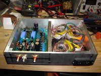
thought I'd post a quick progress report. Building the enclosure has been taking most of the time on this project. Last time I corresponded with Pedja, I told him I thought I'd be done in February, and here we are in March with still quite a bit of work to do! Most of the fabrication is complete, mainly I have to mount the transformers and do the wiring. Then I have to figure out how I'm going to do the final finish (alodine, anodize, etc).
I thought it would be cool to do a small enclosure that just fit the components, but now that I've seen the reclocker, I'm starting to wonder if that was a mistake, as I'm not sure if that will fit or not.
In any case, the enclosure definately has a nice heft to it. It is made of Aluminum T6061, with the panels between 1/4 and 1/2 inches thick. I'm sure it could easily survive being run over by my car.
Attachments
Has anyone tried to substitute the 14 1541-caps with so,ething lie a 1uF Mundorf Supreme or other type of cap which you would consider state-of-the-art in a a normal amp-coupling-application ? It would consume space...a lot of space...but wouldn't it be the ultimate ?
I've tried a few different types for the msb/lsb caps and always reverted back to the ones Pedja recommends
Nice case bzo😎
Nice case bzo😎
Member
Joined 2002
- Status
- Not open for further replies.
- Home
- Group Buys
- TDA1541A non-o/s DAC PCB