Just working on this. I will upload the schematic, parts list and components outlines (as above but like 1:1 scaled pdf) to my site in a few days (will post here info when I upload it). This will keep preview status but I believe it will be practically the final version.
Schematic, parts list and pcb top overlay is uploaded now.
http://users.verat.net/~pedjarogic/audio/tda1541a_dac/tda1541a_dac_rev.htm
I have checked all a few times (what a pain!) but it is possible that something passed my attention, so if someone sees something suspicious, please, let me know.
I have also uploaded new page with info about the discrete I/V I have mentioned earlier in this thread.
http://users.verat.net/~pedjarogic/audio/tda1541a_dac/disdia_i-v.htm
Pedja
I want one ! Excellent job, Pedja. Thanks for the time and effort you put in this. When and where can we order ?
BTW do some of the regulators need coolers ? Not enough time to look into it now but IC 6 is close to C17, that's why I ask.
BTW do some of the regulators need coolers ? Not enough time to look into it now but IC 6 is close to C17, that's why I ask.
Thanks Jean-Paul,jean-paul said:I want one ! Excellent job, Pedja. Thanks for the time and effort you put in this. When and where can we order ?
Just a bit of patience, I would like to make at least one board working to be sure everything is right. This will save both me and others of potential problems. The first board will be finished tomorrow and I hope I will populate it in a few days.
BTW do some of the regulators need coolers ? Not enough time to look into it now but IC 6 is close to C17, that's why I ask.
Well noticed, I must say! I simply could not resist to put that regulator in row with IC4 and IC5. [joke… ok, partially it is not]
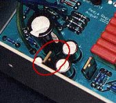
This is the situation. With R12=220R the current through IC6 is about 40mA which will lead to, if we are inside the suggested secondary voltage for this rail, 200-250mW dissipated power on the regulator (that is why the range of the suggested voltages for this secondary is tighter than for the others). For TO-220 package this is quite acceptable and the heat goes up and a majority of the caps of this capacitance (somewhat smaller capacitance might be used as well) are shorter than the regulator. The regulator can always be sloped ahead and if someone insists there is a place for TO-220 heatsink (U shaped, but I really think this will not be necessary). I have in the previous board similar situation with 24V regulator (pic below), it is a bit warm there but everything works fine. I even firstly used 180R (as shown in the schematic of the first project’s supply), and later I did put 220R here but this was rather because of TL431 (though it still could work and IME TL431 likes the current).
Pedja
Attachments
Hi Pedja, excellent work 🙂.
I particularly like the method of tying Va+ to Vd+ with diodes, as I've had latch-up with Crystal devices in the past.
Something I forgot to ask about was whether the SPDIF gnd connection can be broken. I use balanced interconnects. If it's too late, don't worry, I'll find a way 😉
I particularly like the method of tying Va+ to Vd+ with diodes, as I've had latch-up with Crystal devices in the past.
Something I forgot to ask about was whether the SPDIF gnd connection can be broken. I use balanced interconnects. If it's too late, don't worry, I'll find a way 😉
Hi John,dhaen said:I particularly like the method of tying Va+ to Vd+ with diodes, as I've had latch-up with Crystal devices in the past.
I personally did not have this problem but these diodes are something like my insurance.
I hope this pic answers your question.Something I forgot to ask about was whether the SPDIF gnd connection can be broken. I use balanced interconnects. If it's too late, don't worry, I'll find a way 😉
Pedja
Attachments
Re_ the ordering
I did not plan anything special about this, you can place the order using a simple e-mail. But again, it is still early for this. The Wiki page looks better than I have expected and there are also some AFAICS seriously interested for board in this thread who are not signed in Wiki. I also have some interest received by mails and all this will push me to deal more seriously with the ordering/shipping issues and I will dedicate some time to this after the designing work is finished.
And thanks to all for believing in me and for the kind words I received in this thread, I am not sure I can always recognize myself in these.
Pedja
Finished as expected a few days ago but it took some time to make the picture.
Higher res pic here:
http://users.verat.net/~pedjarogic/audio/tda1541a_dac/tda1541a_dac_rev.htm
An externally hosted image should be here but it was not working when we last tested it.
Higher res pic here:
http://users.verat.net/~pedjarogic/audio/tda1541a_dac/tda1541a_dac_rev.htm
Why no option for smaller bypass caps? Those are pretty big.
Otherwise really nice looking board😉
Otherwise really nice looking board😉
Thanks. And thanks.
Any other smaller MKP?
Btw, it is not a problem to make the board that could accept parts of different size. But it is a problem to make it to get the best layout in all the cases. Actually you finish with the solution that is the compromise with something that will not be actually used. So if I would decide to use MKP4, I would in fact be sorry not to make layout tighter (they are not only shorter but also thinner).
Pedja
Else than those for MSB, the footprints are for WIMA 0.1u/250V MKP10. It is true MKP4 for example are smaller but MKP10 are (supposedly, at least WIMA claims so) better for pulse applications. But the fact is I could put additional set of pads.Peter Daniel said:C105 - C 118
Any other smaller MKP?
Btw, it is not a problem to make the board that could accept parts of different size. But it is a problem to make it to get the best layout in all the cases. Actually you finish with the solution that is the compromise with something that will not be actually used. So if I would decide to use MKP4, I would in fact be sorry not to make layout tighter (they are not only shorter but also thinner).
Pedja
- Status
- Not open for further replies.
- Home
- Group Buys
- TDA1541A non-o/s DAC PCB