The reason I gave importance to this is that I think this could really make problems. You will easily find 15mm MKP but you will not that easily find ones 5mm or less wide.
I have not settled on what I settled in a minute or two. If memory serves me well, when I was playing with this I have that issue, if I wanted to keep decently sized tracks between the TDA and these caps, yet 6mm wide caps meant they will be at least a few mm farther from TDA – they have been spreading more left and right looking from TDA’s pins and the routing of these tracks became more problematic.
Maybe the alternative could be some smaller (lower voltage) axial pieces.
But don’t forget that as long as you do not decide to use one cap up - on cap down strategy, you need caps wide 5mm or less.
Pedja
Pedja said:
What is interesting about MKP10 0.1u/160V is the fact Buerklin gives the same dimension for these like for 0.1u/250V while WIMA datasheet claims something else.
http://www.buerklin.com/gruppene/KapD/D103240.asp?l=e
http://www.wima.com/wimaforhcr.pdf
Mouser confirms WIMA’s data:
http://www.mouser.com/catalog/617/451.pdf
What are the real dimensions? Or are there two same capacitance/voltage pieces of the different dimension? It is specified sometimes in WIMA’s datasheets, not in this case though.
I guess it is not a problem to use values somewhat higher than 0.1u at all the pins but I do not know if thus something will be gained or not.
Pedja
Having an actual Wima .1uF 160V cap in my hand, and my set of calipers to measure.. this is what I get:
Width: 4.95mm
Length: 17.98mm (of body)
Height: 10.96mm
Lead spacing: aprox 15mm (15.85mm outer edge of leads)
Lead diameter: .81mm
Hmmm... just went to Mouser to see what they say, and it DOSEN'T match.. went to Wima and it's the same.. The interesting thing is that the package size is the same as what they have for 250v models, 5x11x18 and 15 spacing, as opposed to the 160v that should be 6x12.5x13 and 10mm spacing.
Yet, it's marked as a 160v part. Wonder if they decided to quit the other size, and just market 250's as 160? Are my parts old (have no idea how long they've been in that drawer at my work) and there is a new size now? A mystery... and I was hoping to clear things up..
The voltage rating of course isn't an issue, but will the wider (6mm vs 5mm) parts have spacing problems on the board? If not.. no problems.
On the other value question.. I have seen some builders of this chip state that .22uF possibly sounds better... and one guy saying that .33uF was getting worse again, but I have no direct idea how true this may or may not be. TDA1541A parts datasheet shows .1uF at that location.
There is a Wima .22 160v that is 7x14x18 and 15mm spacing, if it isn't too wide, but Mouser dosen't stock them.. have to go to Wima or a distributor.
I feel i must agree with Jean-Paul - if something is to be done do it on the next revision. Pedja has done a lot of work so far (and very impressive it looks too!) and i feel its too much to ask him to alter it. Im quite sure we can all find/buy suitable caps to fit.
I checked something about the dimensions of WIMA’s and there is a bit of confusion here. They definitely have some values that are (or were) manufactured in a few packages (3 in some cases) and not all packages are listed in their datasheet and 0.1u/160V MKP10 is obviously among them. Maybe (just a guess) Mouser sells 15mm leads spacing units, maybe they just rewrote the data from the datasheet?JonPike said:Having an actual Wima .1uF 160V cap in my hand, and my set of calipers to measure.. this is what I get:
Width: 4.95mm
Length: 17.98mm (of body)
Height: 10.96mm
Lead spacing: aprox 15mm (15.85mm outer edge of leads)
Lead diameter: .81mm
Hmmm... just went to Mouser to see what they say, and it DOSEN'T match.. went to Wima and it's the same.. (…)
Once again: 6mm wide parts won’t fit for C105-C110 and C113-C118, 5mm is maximum here. C111 and C112 could be 6mm wide. The units I use here are Bürklin parts # 43 D 222.
Bzo, from the Digi-Key’s catalog pages you have linked it seems like BC Components MMKP383 0.1u/250V (Digi-Key # BC1812-ND) will fit very well. Possible alternatives are BC MKP417 0.27u/160V (DK # BC2118-ND) and BC MKP418 0.15u/250V (DK # BC2160-ND). As I can see all are on stock. I couldn’t see anything from Panasonic that will fit though.
Pedja
OK.. If it's 5mm max, it's 5mm max..
So someone needs to talk to Mouser, and find out if they have the 5mm wide 15mm lead spaced parts or not.. as well as talk to a Wima rep in regards to where to find the .1uf 250v parts that are "officially" that size... I've gotten too busy at work the past few days to squeeze that in, or I'd do it tomorrow..
So someone needs to talk to Mouser, and find out if they have the 5mm wide 15mm lead spaced parts or not.. as well as talk to a Wima rep in regards to where to find the .1uf 250v parts that are "officially" that size... I've gotten too busy at work the past few days to squeeze that in, or I'd do it tomorrow..
Pedja, is C19' on the back side of the board? If so, what is the footprint of that component? I think I'm going to start ordering some components soon.
thanks for looking at those BC Components parts btw.
thanks for looking at those BC Components parts btw.
Yes and it goes directly between the pins 5 and 15, so there are no pads for it. Some axial part about 20mm long might be here more convenient than radial one.
For those of you in North America, I just got a quote back from Victoria Magnetics on the following transformers, including mounting hardware. I'm not sure why I didn't spec the extra 5V line for the reclocker at 2A, but it probably has a negligable effect on the price to do so.
Transformer 1 - $94
2 8V @ 1A
3 8V @ 1.5A
1 22V @ 2A
2 17V @ 1.5A
Transformer 2 - $91
2 8V @ 1A
3 8V @ 1.5A
1 22V @ 2A
Transformer 1 - $94
2 8V @ 1A
3 8V @ 1.5A
1 22V @ 2A
2 17V @ 1.5A
Transformer 2 - $91
2 8V @ 1A
3 8V @ 1.5A
1 22V @ 2A
Tda1541a non-o/s DAC PCB
HI BZO,
when I design my PCB & test the power transformer for the tube I/V stage & Digital stage.
I test several different power transformers.
All were high quality.
I test in same watt of EI, c-core, circle core & R-core.
At last I choose of R-core because compare the sound quality.
The R-core was the sec. best. C-core is the best but expensive.
EI had the best punch/bass quality of all transformers.
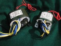
the photos show was the r-core I choose for my parallel TDA1541A PCB use. Every kit will use two R-core power transformers.
I prepare to sell to all diyers for USD 100 per pair include postage post worldwide.
Every power transformer is 25 watt power.
thanks
thomas
www.diyaudiocraft.com
HI BZO,
when I design my PCB & test the power transformer for the tube I/V stage & Digital stage.
I test several different power transformers.
All were high quality.
I test in same watt of EI, c-core, circle core & R-core.
At last I choose of R-core because compare the sound quality.
The R-core was the sec. best. C-core is the best but expensive.
EI had the best punch/bass quality of all transformers.
the photos show was the r-core I choose for my parallel TDA1541A PCB use. Every kit will use two R-core power transformers.
I prepare to sell to all diyers for USD 100 per pair include postage post worldwide.
Every power transformer is 25 watt power.
thanks
thomas
www.diyaudiocraft.com
Attachments
Pedja, I just noticed that you put some new pictures of the populated boards on your web site. Looks nice! Is it operational yet?
Hello BZO,
Yes, it is working a few days already. Sounds pretty nice but I still have to check some things. Will post here more info in a day or two.
Btw, I bought my 150W, 8 secondary windings Xformer for 40EUR (and this price was higher than the previous time).
Pedja
Yes, it is working a few days already. Sounds pretty nice but I still have to check some things. Will post here more info in a day or two.
Btw, I bought my 150W, 8 secondary windings Xformer for 40EUR (and this price was higher than the previous time).
Pedja
40 EUR! Blimey thats good. I have no idea how much a transformer like that would be in the UK. Probably a lot. Can seperate transformers be used?
Pedja said:Hello BZO,
Yes, it is working a few days already. Sounds pretty nice but I still have to check some things. Will post here more info in a day or two.
Btw, I bought my 150W, 8 secondary windings Xformer for 40EUR (and this price was higher than the previous time).
Pedja
Rotellian said:40 EUR! Blimey thats good. I have no idea how much a transformer like that would be in the UK. Probably a lot. Can seperate transformers be used?
OK I am salivating already, how long until we can see a PCB price and shipping deadlines?
🙂 🙂 🙂
Anthony
How about the Rifa SMR caps.
Hi all,
The Rifa SMR cap series seems to be quite suitable for this purpose, at least in size. They come in 63v and up to 1uf. I have use those in decoupling ps but didn't compare it to any other caps, so I couldn't say how good those are. They can be found at Farnell.
Hi all,
The Rifa SMR cap series seems to be quite suitable for this purpose, at least in size. They come in 63v and up to 1uf. I have use those in decoupling ps but didn't compare it to any other caps, so I couldn't say how good those are. They can be found at Farnell.
Yes, why not.Rotellian said:Can seperate transformers be used?
All signed to the wiki page, those who showed the interest in this thread and those who e-mailed me during the previous weeks, can be sure they have reserved their samples, but I rather will not process all the orders immediately, I will rather not have more than about 10 at one moment (simply I do not have an idea what can go wrong). You will be informed about when you could place an order and no tight deadline will be set.Coulomb said:OK I am salivating already, how long until we can see a PCB price and shipping deadlines?
The price of the board is 25EUR. Shipping to Europe by registered mail costs about 8EUR, for the rest of the world it is about 10UER.
There is another option for those in the North America. Friend of mine travels to the US at the end of May, and can send the boards from there so the shipping cost could drop to the local level. I would also consider this way of sending somewhat safer.
I will post more info about the board itself later today, eventually tomorrow. I was busy with it and still have not get far setting the economical side of the stuff. What I know at the moment is that the payments can be made using Western Union, for anything else (considering both payment and shipping methods) you should wait for some time for more info.
I have checked shortly and as I can see the units with 15mm lead spacing have minimum width of 5.5mm, so as long as they are not more thin in the real world, they won’t fit.ChuckT said:The Rifa SMR cap series seems to be quite suitable for this purpose, at least in size. They come in 63v and up to 1uf. I have use those in decoupling ps but didn't compare it to any other caps, so I couldn't say how good those are. They can be found at Farnell.
Pedja
Did I or anyone mention these yet? BC Electronics 2222 416 11304 and 11504 (.13uF and .15uF) 63V Polyproplyne, are 5.0mm wide, 11mm high and 12.5mm wide, with a 10mm pitch, and Digikey stocks them..
The .1uF is 6mm wide and shorter pitch.. but the wider format of the larger ones gets them back to 5mm for just these two values.
Another useable option?
The .1uF is 6mm wide and shorter pitch.. but the wider format of the larger ones gets them back to 5mm for just these two values.
Another useable option?
Hi all,
It was not easy and comfortable decision, but I have decided to go with another prototype. Yes, as I said, this one does not sound bad at all, but I switched back to some things I have made earlier and switched forth and back and forth and some things I did earlier work better. I am not quite sure what could be the reason for this, but, else than I am still thinking about possible bad consequences of the ground plane, and case made of black aluminum about which properties I know nothing but it is the magnetic material, the most possible option is the problem with close proximity of the analog stage and the digital circuitry.
Technically, I found some problems with AD844 used as common base stage and its source is found in the chip’s output stage. (No such problems were encountered using this chip as a classic current feedback opamp but interestingly, in these circumstances which also included the current source for offset nulling, I liked better the sound of lower speed OP27.) On the 20MHz scope everything yet looks fine. I could check it with 60MHz unit soon but I am not optimist that I will still see anything with it, the problem might easily reside somewhere higher. However, the problem is observable using FFT analysis inside the audio range like a 100Hz sidebands around the sinewave and/or its harmonics (this is not a normal ground loop) and generally higher harmonic distortion level than it can be seen at the unbuffered AD844’s output. Short look back on the measurements I made points out that this misbehave was present, though in lesser degree, also in my previous 1541A DAC (and apparently have passed my attention), but now this ugly event was triggered in a more determined way.
So, this practically means also one good thing: the harmonic distortion of the first stage appeared to be somewhat lower than that I have measured previously for the whole AD844 chip. Since achieved figure is less than 0.07%, I am prone to leave for some time idea of dealing with discrete common base stages for this DAC. Now, the obvious solution is to take the unbuffered output and to have the results better than expected. However, my findings are that the buffer is good here, embedded AD844’s buffer (even while misbehaving) adds dynamics and authority (though this option lacks some naturalness). This means that I will include in the design the external output buffer. My intention is to include the JFET one.
There are also some measures that can be taken to achieve more decent performance with the AD844’s onboard buffer - shunt cap at the transconductance node is of paramount importance then, and I would go back to classic prevention with the output resistor as well – so the usage of the buffered AD’s output will be left as an option. This means the board will have TDA’s current output, AD’s unbuffered and buffered outputs, and JFET buffered output.
I will take the chance to do the things suggested earlier in this thread as well, so there will be an option to use TDA decoupling caps with different lead spacing. In the next day or two some further suggestions can be accepted but only if they are easily and quickly applicable.
Most of the existing parts, including the transformer, remain the same. I will give my best to do the things now much faster than the first time, thus the boards hopefully will not late more than a few weeks and this project will not turn into a soap opera.
For all those impatient and/or intended not to build anything but an external I/V, the digital part of the existing board plays as good as I wanted, and if there are some of you interested yet for this version, you can contact me by e-mail so I could order one batch of them.
All the others, sorry for the inconvenience but I think this is the better way.
Pedja
A brave and thoughtful decision, I wish most manufacturers would have this attitude.
So you can implement an input transformer now ? 😉 Seriously: maybe the delay as proposed by HtP can be in the new design ?!? And what about Rudolf Broertjes discrete I/V stages ( if he does not mind ) ??
The possibility of using different spacing is OK if it does not compromise the results. No concessions to quality please because people want to use extraordinary parts 😀 An idea could be to design the PCB for a off the shelf high Q type MKP capacitor and deliver the caps with the board as a standard ( like BrianGT did with the Gainclone PCBs ). It'll keep total costs down for the "customers" as well. If people are willing to pay in advance after seeing pics of the board and testresults you don't have to invest huge amounts of money.
Good luck with the new version, don't feel "hunted" because you're not obliged to anyone. Take your time and try to keep the fun in it. We can't complain as we are the ones that let you do the job....
- Status
- Not open for further replies.
- Home
- Group Buys
- TDA1541A non-o/s DAC PCB