So the current spacing on those is 0.60"?
It is fine, but some people just might have some other caps at home and will not proceed with buying those Wimas. Like for instance, I have substantial quantity or ROE MKT caps and those would be OK here, but the spacing on them is 0.30". There is also an alternative for those in US, who want to buy Panasonic caps from DK (as they might be also good in that application) and I guess spacing on those would also be less, as they are not rated 250V.
Of course this is not a big issue, and any way will work, but it would be just more convenient to provide more options for people.
Yes, 0.60” (15mm).
I somehow discarded all the MKSs (MKTs) for usage here and have looked on the possible MKPs. But I will think about this again.
Take note that, though probably not available everywhere, these WIMAs are quite cheap, Buerklin (part # 43 D 642) sells them for 0.3EUR/piece, 0.24EUR for 10 or more, which means 12 needed 0.1u caps cost 3EUR.
It would be useful if anyone can post info about the American suppliers of these.
I will change a bit my plan considering the passive parts, at least for this unit I am soldering, since I stayed without some caps I have ordered. Newark does not sell OS-CON SG anymore, so I will use BG’s NX I have at hand instead (for the receiver and TDA’s digital supplies) which will be, according to Peter’s latest findings good thing. The bad thing is that I will be shortened for more objective insight about the differences produced by the layout only.
Pedja
Ooops...
I meant Farnell (part 664455).Pedja said:Newark does not sell OS-CON SG anymore (...)
Did a quick check, and the only large vendor I could find for those WIMA caps in the USA was Mouser. Unfortunately, they don't carry the 250V .1uf MKP10.
By the way, is the value for these decoupling caps critical? I seem to recall seeing some people using larger values for a few of the LSBs.
By the way, is the value for these decoupling caps critical? I seem to recall seeing some people using larger values for a few of the LSBs.
Tda1541a non-o/s DAC PCB
hi,
I know that the de couple cap of the tda1541a large will use 1uf.
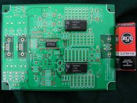
due to many diyer had different taste, so I design my TDA1541a PCB was fit for different size cap. The large was wima.
pls see the lay-out of my PCB. the 4 pin holes beside the TDA1541a was fit for different size & different value of the de-couple caps.
otherwise, more grounding area will better.
thanks
thomas
hi,
I know that the de couple cap of the tda1541a large will use 1uf.
due to many diyer had different taste, so I design my TDA1541a PCB was fit for different size cap. The large was wima.
pls see the lay-out of my PCB. the 4 pin holes beside the TDA1541a was fit for different size & different value of the de-couple caps.
otherwise, more grounding area will better.
thanks
thomas
Attachments
Mmm, now that I read the latest posts I understand some of the wishes. Normally I would use Wima MKP10 0.1 uF 160V so I won't be able to use them. But in case of a nice layout that will be worse when edited I would advise you to make this PCB an as-is offer. The caps are not that expensive and/or hard to get. BTW the best caps are big, aren't they ? 😉
Do not edit the board in this stage to cater for anyones wishes. It will slow down things and chances are that it will be an neverending story leaving Pedja with a bad feeling. Everybody has different wishes and if you want to incorporate all those wishes the board will never be finished. It is impossible to keep everybody satisfied and you need the time for testing/measuring/debugging the DAC which seems more important. It is a bad experience to ship something and later discover it has flaws.
If people want a board they should accept what you offer at the moment or design a PCB themselves ( or hardwire ). Maybe next time it is wise to show the design in an earlier stage leaving room for suggestions.
edit: I just checked and 0.1 uF 160V MKP10 fits on the PCB, just as 0.1 uF 250V MKT and even 0.1 uF 630V MKT provided that 15 mm is the correct format. It seems bigger at the picture. 15 mm spacing is pretty standard in MKP, in many cases it'll be only MKT that is smaller ( till 5 mm spacing ).
hi paul,
I did not know this message U was talking to me or not.
But really, I design this PCB only like to design a good PCB to diyer.
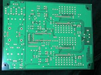
the photos show was the back screen. U can see the de-couple cap was also shield by the grounding to lower the noise.
thisPCB is test print I added more functions which compare with the standard specification that at first posted on this forum.
1. include I2S input which was very close the CS8414 to prevent the data error during passing the message.
SYN-SCK-SDATA.
Reclocking input also reserve for my coming reclocking parts.
I was waiting for my japan friend posting lower than 30PPM crystal to me to build the reclocking parts.
Diyer can make choice use or not.
for more information, pls visit.
http://www.sakurasystems.com/
2. added one dip.switch.
for setting for different mode.
syn mode or aysyn mode.
3. I tested that the input pulse transformer is much better than use a 75ohm resister. The T1 space on the PCB at first I deside come with the RS Pulse (H.F.) 75ohm input transformer. Ratio is 1:1.
But recently I received some news & due to I had links with japan many brand audio transformers.
I received that Tamura had one new developed Pulse transformers which design for the digital interface for professional audio equipment as prescribed in EIAJ standards.
the band width is more width than RS.
Tamura from 100Khz~6MHz. Its made by Amorphopus core.
I was waiting for the sample.
If the price that japan offer to me is good. I will use into the kits.
thanks
thomas
www.diyaudioicraft.com
If people want a board they should accept what you offer at the moment or design a PCB themselves ( or hardwire ).
I did not know this message U was talking to me or not.
But really, I design this PCB only like to design a good PCB to diyer.
the photos show was the back screen. U can see the de-couple cap was also shield by the grounding to lower the noise.
thisPCB is test print I added more functions which compare with the standard specification that at first posted on this forum.
1. include I2S input which was very close the CS8414 to prevent the data error during passing the message.
SYN-SCK-SDATA.
Reclocking input also reserve for my coming reclocking parts.
I was waiting for my japan friend posting lower than 30PPM crystal to me to build the reclocking parts.
Diyer can make choice use or not.
for more information, pls visit.
http://www.sakurasystems.com/
2. added one dip.switch.
for setting for different mode.
syn mode or aysyn mode.
3. I tested that the input pulse transformer is much better than use a 75ohm resister. The T1 space on the PCB at first I deside come with the RS Pulse (H.F.) 75ohm input transformer. Ratio is 1:1.
But recently I received some news & due to I had links with japan many brand audio transformers.
I received that Tamura had one new developed Pulse transformers which design for the digital interface for professional audio equipment as prescribed in EIAJ standards.
the band width is more width than RS.
Tamura from 100Khz~6MHz. Its made by Amorphopus core.
I was waiting for the sample.
If the price that japan offer to me is good. I will use into the kits.
thanks
thomas
www.diyaudioicraft.com
Attachments
Hi Thomas, I was adressing to Pedja of course as this is "his" thread discussing his design. Please discuss your board in your thread as crossing the subjects will work confusing.
I don't know Tamura digital pulse transformers but I think 6 MHZ is poor compared to the established brands. The ones I use have 340 MHz bandwidth. Audiobrands like Tamura and Audio Note produce very fine transformers but I think the field of pulse transformers is better left to specialists in that area. Of course this is just my opinion which might be totally wrong.
I don't know Tamura digital pulse transformers but I think 6 MHZ is poor compared to the established brands. The ones I use have 340 MHz bandwidth. Audiobrands like Tamura and Audio Note produce very fine transformers but I think the field of pulse transformers is better left to specialists in that area. Of course this is just my opinion which might be totally wrong.
jean-paul said:edit: I just checked and 0.1 uF 160V MKP10 fits on the PCB, just as 0.1 uF 250V MKT and even 0.1 uF 630V MKT provided that 15 mm is the correct format. It seems bigger at the picture. 15 mm spacing is pretty standard in MKP, in many cases it'll be only MKT that is smaller ( till 5 mm spacing ).
OK, you guys have already found the .1uF 160V caps.. I was going to mention here in the US, Mouser stocks them at something like $0.53 each.
We have some of these at my work.. and a high end LCR meter.. the MKP10 caps are about 1/10th the ESR of good ceramics and even polyester film caps. Polyproplyene and good design.. makes for a great cap..
So, when is this board going to be available?
Jon
Tda1541a non-o/s DAC PCB
hi paul,
can U tel me which transformers had 340Mhz band-width.
I had audio-consulting digital transfortmer. Still cannot run in 340mhz.
which one U are using.
thanks
thomas
hi paul,
can U tel me which transformers had 340Mhz band-width.
I had audio-consulting digital transfortmer. Still cannot run in 340mhz.
which one U are using.
thanks
thomas
Hi Thomas, have you read the AN-134. There are many SPDIF transformer recommendations on it.
AES and SPDIF recommended transformers
Scientific Conversion Inc
Jensen Transformers
AES and SPDIF recommended transformers
Scientific Conversion Inc
Jensen Transformers
Tda1541a non-o/s DAC PCB
hi banana,
thanks for your information.
But looks the price of all this transformer is quite expensive.
I choose the small 75ohm input transformer was setting use in the standard.kit to relief the 75 ohm resister.
If diyer like to upgrade, i think must upgrade by themself.
Because I considerate DIY kits cannot two expensive.
if DIY kit in high price, I was afraided that users will buy second hand products because they had resell value. Diy kits looks cannot had resell value. So I think the selling price of the kits looks USD 150~200 with EMS postage to overseas & cheaper to hong kong people was best I can was do this.
Include two 1541a, cs8414 all OS-con, dale resisters, Elna gold &
diode use MBR 160 or Schottky.
all this parts I cannot maintain too low price. I only like to produce a good produce to all diyers.
hope diyers will agree.
peter.
I saw some messages was talking about using different size de-couple cap of 1541a. So I post my design that will multiple for different caps. This will easy to all diyers. I only like to share experience to others.
thanks
thomas
www.diyaudiocraft.com
The part with decoup caps was practically left as it was in the previous board. As far as I remember, when I was thinking about the caps for this place, I was looking for as thin as possible piece (I guess it is not hard to understand why) and these 0.1uF/250V appeared as best (I did not use them because I had them at hand…- I have ordered them! 😉).
For C105-C110 and C113-C118 lead spacing is 15mm, available width is 5mm, available length is 18mm (in fact there is some more mm of length, C119 could be mounted beneath the board to make a space for C113/C114). The dimensions are the same for C111/C112 (MSB) with that exception the available width is 6mm thus they fit for WIMA MKS4 2.2u/63V (MKP would be really big in this case).
At one point it was easy to put the additional pads here, ground is just beneath and it could be done literally in one minute, but once you fill top layer with ground plane the things become a bit (b)locked. Now the adding of these pads will turn me back to the point from which is not bad to think about making another prototype (and I am not a factory). I will probably do what Jan-Paul has said and take this into account in the possible next rev.
http://www.buerklin.com/gruppene/KapD/D103240.asp?l=e
http://www.wima.com/wimaforhcr.pdf
Mouser confirms WIMA’s data:
http://www.mouser.com/catalog/617/451.pdf
What are the real dimensions? Or are there two same capacitance/voltage pieces of the different dimension? It is specified sometimes in WIMA’s datasheets, not in this case though.
Pedja
For C105-C110 and C113-C118 lead spacing is 15mm, available width is 5mm, available length is 18mm (in fact there is some more mm of length, C119 could be mounted beneath the board to make a space for C113/C114). The dimensions are the same for C111/C112 (MSB) with that exception the available width is 6mm thus they fit for WIMA MKS4 2.2u/63V (MKP would be really big in this case).
At one point it was easy to put the additional pads here, ground is just beneath and it could be done literally in one minute, but once you fill top layer with ground plane the things become a bit (b)locked. Now the adding of these pads will turn me back to the point from which is not bad to think about making another prototype (and I am not a factory). I will probably do what Jan-Paul has said and take this into account in the possible next rev.
What is interesting about MKP10 0.1u/160V is the fact Buerklin gives the same dimension for these like for 0.1u/250V while WIMA datasheet claims something else.jean-paul said:I just checked and 0.1 uF 160V MKP10 fits on the PCB, just as 0.1 uF 250V MKT and even 0.1 uF 630V MKT provided that 15 mm is the correct format. It seems bigger at the picture. 15 mm spacing is pretty standard in MKP, in many cases it'll be only MKT that is smaller ( till 5 mm spacing ).
http://www.buerklin.com/gruppene/KapD/D103240.asp?l=e
http://www.wima.com/wimaforhcr.pdf
Mouser confirms WIMA’s data:
http://www.mouser.com/catalog/617/451.pdf
What are the real dimensions? Or are there two same capacitance/voltage pieces of the different dimension? It is specified sometimes in WIMA’s datasheets, not in this case though.
I guess it is not a problem to use values somewhat higher than 0.1u at all the pins but I do not know if thus something will be gained or not.bzo said:By the way, is the value for these decoupling caps critical?
Do not expect the board to be available before the end of April.JonPike said:So, when is this board going to be available?
Pedja
Pedja said:Now the adding of these pads will turn me back to the point from which is not bad to think about making another prototype (and I am not a factory). I will probably do what Jan-Paul has said and take this into account in the possible next rev.
Leave it as it is then. If one is desparate to use different caps, they can always drill additional holes and scrape the paint to make new pads.😉
JonPike said:
OK, you guys have already found the .1uF 160V caps.. I was going to mention here in the US, Mouser stocks them at something like $0.53 each.
The mouser catalog lists these as 10mm leads, which if correct, won't fit on the current board.
hi pedja,
nice board! 😎
i'm now doing a new 1541 board design and facing the same problem that whether i should cater different lead pitch for those decoupling caps. 😕
cheers
nice board! 😎
i'm now doing a new 1541 board design and facing the same problem that whether i should cater different lead pitch for those decoupling caps. 😕
cheers
bzo said:
The mouser catalog lists these as 10mm leads, which if correct, won't fit on the current board.
It is quite possible as the 160V caps will have less spacing than ones rated at 250V.
One solution would be to include the 0.1/250 Wimas with the board.😉
DIY the hole you need!? Don't forget to remove there the ground plane from the top layer too. 😉Peter Daniel said:Leave it as it is then. If one is desparate to use different caps, they can always drill additional holes and scrape the paint to make new pads.😉
May this link be of help?
http://www.wima.com/navig/rep.htm
Taw Electronics seems to have 0.1u/250V (type MKP10 0.1uF). But I know nothing about them and/or their conditions.
It doesn't look like the right WIMAs will be easy to acquire in the US. What are some good alternatives? How about the BC Components MMKP 383 Series, AC and Pulse Double Metallized Polypropylene Film Capacitors?
http://dkc3.digikey.com/pdf/T041/0794-0798.pdf
Peter, were the Panasonics you mentioned, the ECQP also found in the above URL?
http://dkc3.digikey.com/pdf/T041/0794-0798.pdf
Peter, were the Panasonics you mentioned, the ECQP also found in the above URL?
- Status
- Not open for further replies.
- Home
- Group Buys
- TDA1541A non-o/s DAC PCB