How can you tell the date?
Mine are Taiwanese, and might be quite late too.
TDA1541A
41105
HSH0412 2
Sounds alright to me though. They work (which helps ;-)
Cheers,
Phil
Mine are Taiwanese, and might be quite late too.
TDA1541A
41105
HSH0412 2
Sounds alright to me though. They work (which helps ;-)
Cheers,
Phil
Can you post a photo?
According to the usual coding they should be from week 12 of 2004.
Cheers
Andrea
According to the usual coding they should be from week 12 of 2004.
Cheers
Andrea
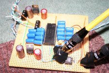
Here's the picture, its in my first ever DAC, so no comments about the build quality!...
I have four of them, they seem to work well to me (although I have never had the opportunity to use the older ones, so I have a limited frame of reference).
It shouldn't, in theory, make too much difference where they are made. It might be though that the process has progressed and the die size is smaller (makes the chip cheaper) - but I would imagine that is very unliekly as it would cost a fortune to respin the chip for such a low volume.
Maybe they made a one off batch of a few thousand, just for small customers? Very nice for a major semi vendor.
Cheers,
Phil
Attachments
Hi,
if it works without Cosc (pin 16-17) it is likely to be a remarked 1541, if it doesn't it's a real 1541A. Easy check.
cheers
Andrea
if it works without Cosc (pin 16-17) it is likely to be a remarked 1541, if it doesn't it's a real 1541A. Easy check.
cheers
Andrea
Andrea,
You have me worried now!
I will try tonight.
I suppose, if it is a non A chip, then at least there is room for improvement!
Cheers,
Phil
You have me worried now!
I will try tonight.
I suppose, if it is a non A chip, then at least there is room for improvement!
Cheers,
Phil
I'm gutted!
Last night, I snipped the leg of the 470pF capacitor, and it still worked!
So I guess these are 1541's then. I bought mine from a (I thought) reputable seller.
So, where can I get a proper one then? I guess I may well be looking for old CD player just for the DAC.
At least it can sound even better!!
😀
Cheers,
Phil
Hi Phil,
in post 59 of this thread are described some differences between the 1541 and 1541A.
http://www.diyaudio.com/forums/showthread.php?postid=371755#post371755
To have a definitive proof you should test with pin 4...
I will disconnect the cap from pins 16-17 on my 1541A DAC to see if your test is repeatable ;-)
Having both 1541 and 1541A I could double check your findings.
Cheers
Andrea
There may yet be hope then.
I don't believe I connect anything to pin 4 (I might be wrong) SCLK is essentially MCLK right?
But I do believe having trouble initially, perhaps with pin 27 (#OB/TWC), but might of had to put data into pin 4 (basically connected pin3 to pin4, but that might of been experimenting to get it right, and then I undid it).
Having said that, I definitely don't use any signals other than BCLK, WS, DATA (i.e. I don't use SCLK).
I will have another look tonight.
If you could double check as well - that would be great, but no hurry.
Cheers,
Phil
I tried running the TDA1541A without the cap and... it still works!
After a momentary puzzling I also noticed that with the cap disconnected there is a sort of background noise , kind of "fizzzzzz".
Thinking better about it the DEM is used to calibrate the current sources, so probably the chip works even without it but the uncalibrated current sources give degraded performance.
Try with just one leg of the cap soldered, if you experience the same result then you have a real "A" chip
Hope we found the solution!
Cheers
Andrea
Hi Andrea,
Yes, I had that puzzling moment, but was too depressed to listen out for any differences.
I'll retest tonight.
The same company sells TDA1541s (non A), so I'm tempted to see if I can hear a difference that way.
Cheers,
Phil
Yes, I had that puzzling moment, but was too depressed to listen out for any differences.
I'll retest tonight.
The same company sells TDA1541s (non A), so I'm tempted to see if I can hear a difference that way.
Cheers,
Phil
inverting
Hello!
I want to invert the phase of the output voltages (so I can use fewer component to the i/v converter at the outputs). Is there any simple solution? Maybe it is enough to invert the SDATA?
Please help me!
Cheers,
Istvan
Hello!
I want to invert the phase of the output voltages (so I can use fewer component to the i/v converter at the outputs). Is there any simple solution? Maybe it is enough to invert the SDATA?
Please help me!
Cheers,
Istvan
Well, I don't really know DACs, but I already read that inverting the signal will work. Also use a non-inverting buffer with the same timings on the other signals to keep everything synchronized(For the positive and negative DACs).
I don't need symmetrical outputs.
I will order two TTL ICs:
74F02 NOR GATE for the SDATA and
74F32 OR GATE for the sck & fsync
I want to short the inputs to get inverter and non inverter gates.
They are in the same TTL family so their delays are close to each other (3,2 and 4ns). Thank You for the idea!
But what is happening if I don't use non inverter gates/buffers? It produces jitter?
Not sure, it should work, maybe producing jitter like you say, but isn't it better to keep everything is sync just to be sure?
I see you're going to use OR gates, so to be sure you have the same timings, you could just use the same OR gates and pull the other pin high or low if you want an inverted signal or not. I thought you were going to use something like a 74x04 hex inverter
I see you're going to use OR gates, so to be sure you have the same timings, you could just use the same OR gates and pull the other pin high or low if you want an inverted signal or not. I thought you were going to use something like a 74x04 hex inverter
Yes, I can use only one exor gate: 74F86. It's the best solution!
With the bottom switch I can choose the correct phase (depend on the actual i/v converter).
An externally hosted image should be here but it was not working when we last tested it.
With the bottom switch I can choose the correct phase (depend on the actual i/v converter).
- Status
- Not open for further replies.
- Home
- Source & Line
- Digital Line Level
- TDA1541 info