Miro is prolific 🙂
One pcb to try more as I have a Marantz cd50 moded (so tda1540) ::: those dac chip have a nice organic sound despite it's 14 bits 🙂
(use pps/acrylic decoupling for the TDA chips please 🙂 )
One pcb to try more as I have a Marantz cd50 moded (so tda1540) ::: those dac chip have a nice organic sound despite it's 14 bits 🙂
(use pps/acrylic decoupling for the TDA chips please 🙂 )
Hi Nrik
Thanks for the report 🙂
Could You please draw the working, corrected SCH?
I am aking because I want to build and comprae to the CPLD that I am using now for the same purpose.
Thanks.
.
You could add decouplind C at each IC power pin to ground. To reduce ground bounces and maybe hear any sound difference?
.
Hi Zoran
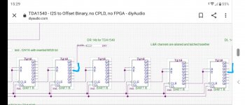
Here is what I did different from the original schematic from Miro's original post (two ligt blue markings). Sorry about the picture quality...made from my phone being at home with the family.
It was testet with a CS8416 input receiver from a cheap small-form-factor China DAC, feeding this circuit which then fed the decoder PCB from a Bang&Olufsen CDX ( similar to Philips CD104 decoder PCB)
The source was a Pioneer CD recorder.
I did only test it the last 5 minutes of the workday, but I have been fiddling a lot with SPDIF receivers, I2S bus and DAC chips the last couple of months to know when things actually work. I did not have time to measure anything yet, but I will see if my old scope can show the square waves nicely on Monday.
I have also purchased the CDES converter PCB with a Xilinx processor and tried that, and actually Miro's circuit works better. The CDES needs a delayed powerup of the spdif receiver, otherwise it locks up with no sound.
Miro's circuit doesn't...it just works!
Of course it would be good to add some power supply caps, but I doubt that it would make it sound better.
It is CMOS chips (not TTL) which uses next to nothing in current.
And even if Miro was worried about high frequency issues we are only talking about 1,5-2 MHz it is not that much, and the HCT series handles up to 25 MHz , so I expect that the square waves will be very square when measured.
Attachments
I am actually more excited too see how it handles a 24 bit signal and higher sampling frequency as well, but I am sure it will be fine.
Important note regarding my test: I fed the TDA1540s directly, so no SAA7030 and no oversampling, because this is the best sound in my opinion. Please note you need to change the anti-alias filter to a lower frequency if you skip the SAA7030 and go non-oversampling.
Important note regarding my test: I fed the TDA1540s directly, so no SAA7030 and no oversampling, because this is the best sound in my opinion. Please note you need to change the anti-alias filter to a lower frequency if you skip the SAA7030 and go non-oversampling.
I have only the experience with the SAA7030, though I could have tried with IanCanada PCM boards or JLSounds USb to "simultaneous proof mode"... I'm not aknowledged about the starting point alignement of the digital frontend and register to adjust.
so what happen if 24 bits material ? What happen to the last 10 bits for the TDA1540 ? It will be swapped or seen as zero ? (I beleive oversampling is of a less importance I believe for the sound quality than the bit depth from my experience). Red book cds were very good in my Marantz TDA1540 cd player though 🙂
so what happen if 24 bits material ? What happen to the last 10 bits for the TDA1540 ? It will be swapped or seen as zero ? (I beleive oversampling is of a less importance I believe for the sound quality than the bit depth from my experience). Red book cds were very good in my Marantz TDA1540 cd player though 🙂
Last edited:
From my practical experience, building a diskrete dac some time ago, firs few bits are from crucial impotrance. I delibetry put 1% unacceptable high tolerance Rs for R2R ladder net. Of course that with low levels distortion was very hearable. But with trimming just first 2 bits that effect significantly reduced.
.
(It is not solution for trim Rs, I did this just for the experiment ansd live test to snif tha sound. It is impossibile to "trim" for low tolerance because of the temperature dependances and other reasons. The solution for this is to use Rs of much lower tolerances )
;
So that few MSBa are from vital impotrtance AND LE line and timing also. And I think that is better to use stopped clock IF iti is posibile, becouse of less noise as outcome.Like in original time sim. format PHI used.
.
And also i used HCT logic. Measure the sygnal ringing at each point out-in between the ICs. Every point was ringing and with putting R in all points the sound was better. I trim each inter IC route to round edges when device is running. From start to end.
.
BTW
one very "strange" thing is that I measure wery clean 20000Hz square whave at the output of TDA1540, generating from computer test WAV file. I was ammased because I cant measure something like this with any other chip IC dac.
.
.
(It is not solution for trim Rs, I did this just for the experiment ansd live test to snif tha sound. It is impossibile to "trim" for low tolerance because of the temperature dependances and other reasons. The solution for this is to use Rs of much lower tolerances )
;
So that few MSBa are from vital impotrtance AND LE line and timing also. And I think that is better to use stopped clock IF iti is posibile, becouse of less noise as outcome.Like in original time sim. format PHI used.
.
And also i used HCT logic. Measure the sygnal ringing at each point out-in between the ICs. Every point was ringing and with putting R in all points the sound was better. I trim each inter IC route to round edges when device is running. From start to end.
.
BTW
one very "strange" thing is that I measure wery clean 20000Hz square whave at the output of TDA1540, generating from computer test WAV file. I was ammased because I cant measure something like this with any other chip IC dac.
.
One thing I spot with TDA1540 - with same USB/I2S interface and same computer with same soft player, changing sample rates is almost instant after change in the settings of the software. And TDA1540 can play up to 384KHz SR. Probabaly more but I didnt have higher SR options... Any other dac IC is much "slower" in that way.
.
Someone comment the sound of TDA1540?
.
.
Someone comment the sound of TDA1540?
.
Hi Zoran
Here is what I did different from the original schematic from Miro's original post (two ligt blue markings). Sorry about the picture quality...made from my phone being at home with the family.
It was testet with a CS8416 input receiver from a cheap small-form-factor China DAC, feeding this circuit which then fed the decoder PCB from a Bang&Olufsen CDX ( similar to Philips CD104 decoder PCB)
The source was a Pioneer CD recorder.
I did only test it the last 5 minutes of the workday, but I have been fiddling a lot with SPDIF receivers, I2S bus and DAC chips the last couple of months to know when things actually work. I did not have time to measure anything yet, but I will see if my old scope can show the square waves nicely on Monday.
I have also purchased the CDES converter PCB with a Xilinx processor and tried that, and actually Miro's circuit works better. The CDES needs a delayed powerup of the spdif receiver, otherwise it locks up with no sound.
Miro's circuit doesn't...it just works!
Of course it would be good to add some power supply caps, but I doubt that it would make it sound better.
It is CMOS chips (not TTL) which uses next to nothing in current.
And even if Miro was worried about high frequency issues we are only talking about 1,5-2 MHz it is not that much, and the HCT series handles up to 25 MHz , so I expect that the square waves will be very square when measured.
Thanks a lot 🙂
I think that version You are corrected was for 16bit for TDA1541A
Please put some link for "CDES converter PCB with a Xilinx processor"
From the same reasons that You spot (CPLD vs logic IC format converter), that sounds better with classic logic I am interested too to build some other converter.
.
I dont want to be rude dont get me wrong please, but I think that square will not be just "square", but with hard ringing and significant ground bounces. Even measured with standard probe set at 10X and with standard cca capacitnace of maybe more than 100pF
Last edited:
Hi Zoran
You are not rude because you are putting a lot of good arguments to support your stand.
I am now more excited to check the square waves from the circuit.
However I do think the circuit is doing really well, since it performs without major problems, even when I
A: deliberately left out the supply caps
B: used through hole components
C: didn't care too much about length of signal paths and allowed ' messy' wiring underneath the x-or and nand gates.
What sort of general value of resistors are you using? Maybe even different values in various positions?
If you want my comment on the sound of TDA1540, it is very live-like, dynamic and analogue sounding A notch better in these areas than TDA1541 and old R2Rs from BurrBrown and AD, and a lot more than any 1 bit DAC.
I have a-b testet many 1 bits : Ak4309 from PlayStation 1002, some 24 bit AKM, and the newer 32 bit ESS9018m2k and BurrBrown PCM5102. I think all1-bits sounds very similar when they are fitted with identical analogue stages.
I think the reason for the specific sound of TDA1540 must lie in the DEM construction with current generators for each bit. Check out Philips TDA1541A d/a converter information - DutchAudioClassics.nl
for more info.
Hi Zoran
You are not rude because you are putting a lot of good arguments to support your stand.
I am now more excited to check the square waves from the circuit.
However I do think the circuit is doing really well, since it performs without major problems, even when I
A: deliberately left out the supply caps
B: used through hole components
C: didn't care too much about length of signal paths and allowed ' messy' wiring underneath the x-or and nand gates.
What sort of general value of resistors are you using? Maybe even different values in various positions?
If you want my comment on the sound of TDA1540, it is very live-like, dynamic and analogue sounding A notch better in these areas than TDA1541 and old R2Rs from BurrBrown and AD, and a lot more than any 1 bit DAC.
I have a-b testet many 1 bits : Ak4309 from PlayStation 1002, some 24 bit AKM, and the newer 32 bit ESS9018m2k and BurrBrown PCM5102. I think all1-bits sounds very similar when they are fitted with identical analogue stages.
I think the reason for the specific sound of TDA1540 must lie in the DEM construction with current generators for each bit. Check out Philips TDA1541A d/a converter information - DutchAudioClassics.nl
for more info.
use 220ohm multiturn small pot. Set to midlle. The goal is to bare in mind informations of recognizing "1" stae value that is lower than +Vb. And "0" that is little before than GND (0) V. This infos are in the PDF for the logic chips. So we dont need any "straight" square and in any case we dont need ringing at the edges. The square should be rounded a bit. Yes the values could be different, from my findings, that is why i suggest to trim. But they are not so different from 68 ohms to 120 ohms. You will see at first time You check it. 🙂
.
Yes I understand why You left out some elements in the first build. I am making in this way too.
.
Yes I thik that this good sound is coming from BJTs and darlington topologies. Not MOSFETS like contemporary design. And not so dense package. With "more room" for dispersion of HF energy and dissipation? At least I think that is one of the reasons.
.
Try:
2 x 20K from DEM pins with 470pF C to the -18V power. That will draw 0.2mA to DEM pins BUT the sound is (for my op.) better, and eye pattern of scope in the DEM pins looking better showing closer or exact 176KHz Fo at the scope.
🙂
I am intending to try sine DEM Fo input to DEM pins.
.
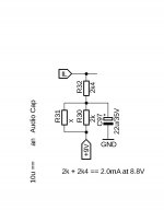
One additional info that may be overlooked: 10mV is max allowed DC offset at the Iout. (Not 25mV as TDA1541A) so the some ma
And current injection of 2mA to the Iout is a must.
.
I think I can project a circuit with stopped clock i will post it.
But it is a great that You assembled working circuit for start and to compare with CPLD modules. Thanks.
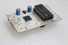
This is the CDES PCB I have tested ( and it has written TDA1540 on the PCB)
Thanks 🙂
Try:
2 x 20K from DEM pins with 470pF C to the -18V power. That will draw 0.2mA to DEM pins BUT the sound is (for my op.) better, and eye pattern of scope in the DEM pins looking better showing closer or exact 176KHz Fo at the scope.
🙂
.
I think I can project a circuit with stopped clock i will post it..
Looking forward to the stopped clock function.
NB: We have two unused X-Or gates if these could be of use.
What are the DEM pins?
And where should the 470pF go?
Would the values be different for 44.1 kHz sampling for us Non-oversampling pirates?
Also: do you have recommendations regarding the supply voltage of TDA1540? (Beside the-18V)?
The data sheet says typically +/-5V and maximum +/-12 V.
I would like to keep the heat low for longer life so I would prefer +/-5V unless you have some performance arguments for +/-12V?
@Nrik,
It's probably the DEM clocking pins Zoran is talking about with John from ECDESIGNS 's circuitry. Often Philips/Marantz tied the two pins for the internal clocking with 470 pF to 860 pF, but it rarely clocks (you have to trim it with an air cap that is too much sensible to the drift with room temperature, humidity rate... so pin 8 & 9
It's probably the DEM clocking pins Zoran is talking about with John from ECDESIGNS 's circuitry. Often Philips/Marantz tied the two pins for the internal clocking with 470 pF to 860 pF, but it rarely clocks (you have to trim it with an air cap that is too much sensible to the drift with room temperature, humidity rate... so pin 8 & 9
@diyiggy
Thanks.
Studied the datasheet for a while... does not really make sense that it rarely clocks (how would the DAC chip even work without?!)
But I will put this in the box called:" too advanced for me at this time, so I will follow others advice!"
Thanks.
Studied the datasheet for a while... does not really make sense that it rarely clocks (how would the DAC chip even work without?!)
But I will put this in the box called:" too advanced for me at this time, so I will follow others advice!"
Hi
What good avialable part will you use for these 2ma injection, please ?
BFA245? J113? ...
Any JFET (pref. low noise) with Idss larger than 2mA. Say Idss=4-6mA or more.
From +5V power to Io dac pin.
I tried BF245B, 2SK170 etc.
But simple R could be used offcourse. Like in some Revox models. 🙂
Last edited:
Looking forward to the stopped clock function.
NB: We have two unused X-Or gates if these could be of use.
What are the DEM pins?
And where should the 470pF go?
Would the values be different for 44.1 kHz sampling for us Non-oversampling pirates?
Also: do you have recommendations regarding the supply voltage of TDA1540? (Beside the-18V)?
The data sheet says typically +/-5V and maximum +/-12 V.
I would like to keep the heat low for longer life so I would prefer +/-5V unless you have some performance arguments for +/-12V?
In almost all of the models using TDA1540 -V is -18V. I tried and there is no overheating. I measure all consumption currenta in working condition and without the digital bus sum of the power stay inside recommended values.
Yes these are DEM pins, where is 470pF C. DEM is dynamic element matching.
.
Last edited:
- Home
- Source & Line
- Digital Line Level
- TDA1540 - I2S to Offset Binary, no CPLD, no FPGA