Finally got two kits!!!
Hi guys,
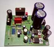
A few days ago I finally got my hands on two TDA7293 composite amplifiers kits from there - Ultra low distortion composite amplifier kits TDA7293 TDA794.
I got the power versions with two TDA7293 in parallel mode, rated 100W @ 4 ohm, THD - 0.00012% (from 0.5 to 90W). There is even a better version of that amp but it was not available at the time of purchase.
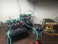
Luckily I got two big heatsinks available and a transformer (22.5-0-22.5) so I immediately hooked the kits up. Dead quiet, nothing, no matter how close I put my ear to the speaker.
Then I tried to measure the THD, though I knew the limitations of my setup - old EMU 0404 USB 2.0, DELL laptop and Arta software. All I got were the noise floor of EMU 0404 and it's own THD. At 100W and 2 ohm load though I managed to measure THD - 0.001% - little bit above the threshold of my setup.
Since I never ever owned an amp with such a low THD, for the listening test I borrowed my neighbor's Q950. Many friends came and a lot of bear cans were dried up, celebrating those little monsters. Some said "it's unbelievable", some said "it's really great" but one thing was absolutely sure - it was not a chip amp sound.
Now I'm going to build a nice enclosure for my new kits, but I just can't stop listen to them. The more i listen the more i like the sound.
Out of curiosity I tried very hard to find out the type of the op amp, that those guys are using. Actually there are two op amps but I believe that the first one serves as a preamp. Anyway both op amps have a kind of a paint or resin on the top. I tried to remove the paint but absolutely no success. Any ideas would be greatly appreciated!
Hi guys,
A few days ago I finally got my hands on two TDA7293 composite amplifiers kits from there - Ultra low distortion composite amplifier kits TDA7293 TDA794.
I got the power versions with two TDA7293 in parallel mode, rated 100W @ 4 ohm, THD - 0.00012% (from 0.5 to 90W). There is even a better version of that amp but it was not available at the time of purchase.
Luckily I got two big heatsinks available and a transformer (22.5-0-22.5) so I immediately hooked the kits up. Dead quiet, nothing, no matter how close I put my ear to the speaker.
Then I tried to measure the THD, though I knew the limitations of my setup - old EMU 0404 USB 2.0, DELL laptop and Arta software. All I got were the noise floor of EMU 0404 and it's own THD. At 100W and 2 ohm load though I managed to measure THD - 0.001% - little bit above the threshold of my setup.
Since I never ever owned an amp with such a low THD, for the listening test I borrowed my neighbor's Q950. Many friends came and a lot of bear cans were dried up, celebrating those little monsters. Some said "it's unbelievable", some said "it's really great" but one thing was absolutely sure - it was not a chip amp sound.
Now I'm going to build a nice enclosure for my new kits, but I just can't stop listen to them. The more i listen the more i like the sound.
Out of curiosity I tried very hard to find out the type of the op amp, that those guys are using. Actually there are two op amps but I believe that the first one serves as a preamp. Anyway both op amps have a kind of a paint or resin on the top. I tried to remove the paint but absolutely no success. Any ideas would be greatly appreciated!
Attachments
the input opamp could be a LM4562 or a NE5532, the first opamp of the composite could be a NE5534 (depends on the compensation-network), but there will for sure other possible types that will work....
Last edited:
Chip amp sound
That is a really great question!!!
The easiest answer is that you have to hear and compare the chip amp sound to discrete amp for example. I'm not saying that it is bad. No, it's just different. For me it brings a kind of a listening fatigue though.
In the same way tube amps /which I don't like much/ have their own signature. Class D amps as well.
Many researchers express the understanding that the "pattern" or "distribution" of the harmonics is what determines the subjective experience.
but there will be fireworks and oscillations with all the rest!but there will for sure other possible types that will work....
Looks like an input buffer and an optional inverter to bring back the whole board to non-inverting.Actually there are two op amps but I believe that the first one serves as a preamp.
I don´t see the reason though to have two additional input buffer/amps.
I guess some people can´t have enough opamps!
New thread about TDA7293
Hi guys,
there is a new thread about TDA7293 composite design - Ultra Low Distortion Composite Amplifiers Based on TDA7293/94
Hi guys,
there is a new thread about TDA7293 composite design - Ultra Low Distortion Composite Amplifiers Based on TDA7293/94
I did a little work on my circuit
I did a little work on my circuit - it took a while, but was worth the effort. This time i reached (almost) the limit of my test-equipment
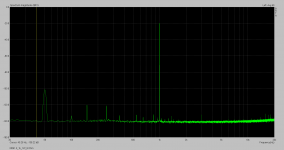
Attachment 1:
- spectrum of a 1kHz sine-Signal 1W at 8 Ohm
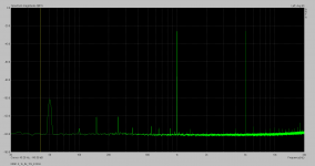
Attachment 2:
- spectrum of a dual sine-Signal 1kHz and 5kHz, 1W at 8 Ohm
Attachment 3:
- spectrum of a dual sine-Signal 18kHz and 19kHz, 1W at 8 Ohm
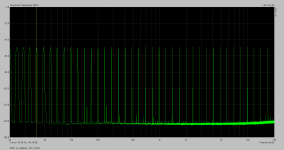
Attachment 4:
- spectrum of a multitone sine-Signal, 1W at 8 Ohm
to do low THD measurements at the amps full power i need a ultra low THD preamp which i do not call my own, so i can't show some right now.
I did a little work on my circuit - it took a while, but was worth the effort. This time i reached (almost) the limit of my test-equipment
Attachment 1:
- spectrum of a 1kHz sine-Signal 1W at 8 Ohm
Attachment 2:
- spectrum of a dual sine-Signal 1kHz and 5kHz, 1W at 8 Ohm
Attachment 3:
- spectrum of a dual sine-Signal 18kHz and 19kHz, 1W at 8 Ohm
Attachment 4:
- spectrum of a multitone sine-Signal, 1W at 8 Ohm
to do low THD measurements at the amps full power i need a ultra low THD preamp which i do not call my own, so i can't show some right now.
Attachments

The limit of my measurement-possibilities is reached.
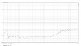
To show this here are the THD-plots of the soundcard tested in loop and the amp loaded with 8 Ohms and 4Ohms.
Attachment 1:
soundcard loop THD, THD appears a little higher as the testing level was not exactly the same as with the amps tests. What i want to show with this diagramm is the rise in THD at the higher frequencies is caused by the soundcard itself
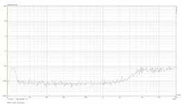
Attachment 2:
amps THD plot with no load on it
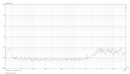
Attachment 3:
amps THD plot with 8 Ohm load @ 1W
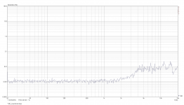
Attachment 4:
amps THD plot with 4 Ohm load @ 2W
conclusion so far:
as the rise in THD at high frequencies is caused by the soundcard itself one should assume that the real THD-plot of the amp stays at the same low level as for the low frequencies. The THD is not as good as with Tom modulus amps, but good enough for me ( as i can use the boards i already ordered in August). To bring the THD down further will be another project.
So the research on this amp is done for me and i am going to build at least 12 of it for my speaker project.
To show this here are the THD-plots of the soundcard tested in loop and the amp loaded with 8 Ohms and 4Ohms.
Attachment 1:
soundcard loop THD, THD appears a little higher as the testing level was not exactly the same as with the amps tests. What i want to show with this diagramm is the rise in THD at the higher frequencies is caused by the soundcard itself
Attachment 2:
amps THD plot with no load on it
Attachment 3:
amps THD plot with 8 Ohm load @ 1W
Attachment 4:
amps THD plot with 4 Ohm load @ 2W
conclusion so far:
as the rise in THD at high frequencies is caused by the soundcard itself one should assume that the real THD-plot of the amp stays at the same low level as for the low frequencies. The THD is not as good as with Tom modulus amps, but good enough for me ( as i can use the boards i already ordered in August). To bring the THD down further will be another project.
So the research on this amp is done for me and i am going to build at least 12 of it for my speaker project.
Attachments
superb job , I bow my head . Only teardrop are the missing component values as most of us here , myself included , will need to find those by trial and error which wont be an easy one .
BUT : GREAT JOB SIR !!!
BUT : GREAT JOB SIR !!!
For sure they are missing - as there is lot of work in this project, finding a topology and adequate values that work well. So everybody who has the idea of building this amp for commercial use has to put some work on it. Otherwise I think about sharing the values for hobbyists like you via a private message.
I repeated the THD measurements of post #130 and found out that the higher THD-reading of the soundcard loop measurement is not caused by a different measurement level. It is the relatively low input impedance of the soundcard that causes the higher THD-reading - so i will have a look in to the soundcard to see what opamps were used and probably change them.
I also tested some other input / error-amp opamps in my circuit (as the question came up for the kaltecs circuit) by using a dual sine signal 19kHz & 20kHz with the level 1W@8 Ohm. The tested opamps performed almost identical in this test. Here are the types tested:
I also tested some other input / error-amp opamps in my circuit (as the question came up for the kaltecs circuit) by using a dual sine signal 19kHz & 20kHz with the level 1W@8 Ohm. The tested opamps performed almost identical in this test. Here are the types tested:
- LM4562 (as the reference for this design)
- NE5532
- TL072
- TL052
- TL082
- TLE2082
- LM833
- OPA2604
- OPA2132
- 2x OPA627 (with an adapter)
- OPA249
- CA3240
Bob will you share board design too? I am also currently building active LR 4th order filter 3way speaker stereo system. For now I designed own LM4766 modules, but it is tempting to try another design.
the board design is in post #55. But as the actual schematic on post #129 differs a little from the board design there are some parts that have to be mounted on top of each other, some others have to be replaced by a piece of wire. I soon will show this on a photo...
By the way - i have some boards left...
By the way - i have some boards left...
Excellent job ! Do you also the values for the components in the schematic ?
I could be also interested by 2 pcb...
Many thanks !
I could be also interested by 2 pcb...
Many thanks !
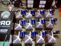
Bernd you have been really busy! Looking really good.
Your PCB reminds me of the Modulus ;-) So many polygons!
Are you planning a 7.1 system or are you already going into production. ;-)
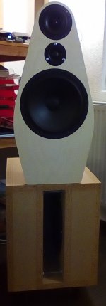
Speaker looks very good too.
Just looked it up in the other thread: Did you omit the BG20?
I think its a good choice. The SLS12 plays quite nice even up to 1k and should more than adequate to meet the B80 somewhere 400-500Hz.
Love that 12" on OB!
Your PCB reminds me of the Modulus ;-) So many polygons!
Are you planning a 7.1 system or are you already going into production. ;-)
Speaker looks very good too.
Just looked it up in the other thread: Did you omit the BG20?
I think its a good choice. The SLS12 plays quite nice even up to 1k and should more than adequate to meet the B80 somewhere 400-500Hz.
Love that 12" on OB!
- Home
- Amplifiers
- Chip Amps
- TDA 7293 -- done right ?