No 7.1-system, stereo is fine for me, even with action movies. The BG20 is replaced by the ScanSpeak 22W/8534G00 because of the lower THD-figure. 2 of the SLS12 at the lower end of the spectrum (and the picture!)
Here is the idea to a little upgrade for my circuit with the input changed to give less noise and an input impedance that is equal for common mode and differential mode signals. Also added is a EMI-filter at the input and fuses in the power supply.
The board has a different layout with the opamps closer to the power amp.
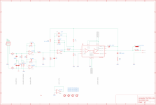
Attachment 1:
schematic of the power supply part
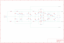
Attachment 2:
schematic of the signal part
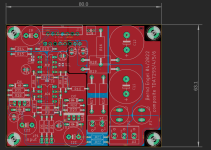
Attachment 3:
board layout
ideas for improvement and comments are welcome!
The board has a different layout with the opamps closer to the power amp.
Attachment 1:
schematic of the power supply part
Attachment 2:
schematic of the signal part
Attachment 3:
board layout
ideas for improvement and comments are welcome!
Attachments

Why the TDA chip is set to multiply only 2 times?
Will it be better to operate IC2B and the TDA chips in inverting mode?
Will it be better to operate IC2B and the TDA chips in inverting mode?
The cause behind the gain of 2 for the local feedback of the TDA was a practical one. With higher gain in local feedback of the TDA the whole amp does not work stable.
For operating both chips in inverting mode i did not find a configuration that has the same (or better) performance than the one shown...therefore i asked about ideas for improvement
For operating both chips in inverting mode i did not find a configuration that has the same (or better) performance than the one shown...therefore i asked about ideas for improvement
As output power mainly is a function of supply voltage and output impedance, power can only be increased by lowering the impedance if the supply voltage don't exceed the ratings of ±50 Vdc. Hence, a BTL configuration will be necessary. Current balancing resistors R3, R16, R22 aren't necessary as per the datasheet.
Best regards!
Best regards!
Sure, that is was i also had in mind. The shown triple is the first step to that. It is able to deliver more current and has a wider area on the power-chips to keep them cool. Here is the proposal for BTL

For sure small opamp chips aren't the most expensive components of a power amplifier. But are U9, U10 really necessary? What about operating U8 in inverting mode instead? And I still spot those current balancing resistors. Have a look at the datasheet, p. 12. Quote: »The outputs can be connected together without any ballast resistor«. It would economize on two Zobel networks per side. Or do you think thery're necessary as you drive each chip directly from the frontend opamp instead of featuring the master-slave mode?
Best regards!
Best regards!
there are a thousand ways to reach the target, and i am almost sure this proposal will work very well. A Zobel on each output i would also use if there were no ballast sharing resistors (for stable operation). As i intend to be able to use the circuit also for TDA7294/5/6 there will be no paralleling like in the TDA7293s datasheet. By driving the chip with a frontend-IC the gain of the power chip can be used for somethin good (lowering THD) as it is typical for composite amps.
Please send me it's schematicsprototype boardwork is done
The prototype boardwork is done. I put the TDA on the edge of the board. But that is only for this prototype, as the pins locations of the TDA is really horrible when mounting it that way.
And as read in several posts in this forum and in neurochromes homepage (taming the LM3886),
there will be room for improvement by shortening the feedbackloop-routes for a more stable operation (thank you Tom) and designing a separate (regulated?) power supply for the input stage of the TDA with a slightly higher (5 to 10V) voltage. This should lower TDAs THD-value (thank you Klaus). As stated above, an edge-mounted TDA is therefore no longer tolerable and work on the direction of the pins needs to be done, because non of the standard pinouts that could be delivered by the distributors are in a direction then needed. But as this is DIY so this is not a problem.
questions and comments to the attached board are welcome.
Bernd
Hello Jijopeter,
if you are looking for the schematics for the words you have quoted - there aren't any. Otherwise read the thread completely and you will find some, Layout and measurements are also shown.
if you are looking for the schematics for the words you have quoted - there aren't any. Otherwise read the thread completely and you will find some, Layout and measurements are also shown.
I got it. Thank you.Hello Jijopeter,
if you are looking for the schematics for the words you have quoted - there aren't any. Otherwise read the thread completely and you will find some, Layout and measurements are also shown.
- Home
- Amplifiers
- Chip Amps
- TDA 7293 -- done right ?