Horizontal spread of the array will largely depend on the driver (size), not much you can do there. Enclosure shape and size will have an influence but not enough to create a wide spread at high frequencies. See: https://www.diyaudio.com/community/...ith-near-field-listening.401247/#post-7400866.I'm planning on curving the array in the hope it'll give me a bit more HF width in both axes.
Would this actually do anything? Does the shading need to stay the same?
If it isn't enough for you, start with a smaller driver. The curving + shading will help with the vertical spread.
Last edited:

The "power shading" you discussed in post #40 would make the two center drivers just over 3dB louder than the outside six. The roughly 200Hz high pass capacitor on the center two would advance the HF by (about) 90 degrees relative to the other drivers, this may be what increased the apparent HF vertical dispersion at 10 feet, at the expense of reduced clarity at greater distance.Thanks. damn.. I'm nearly there. Only need another foot @10 feet.
Bevels and horn/flare shapes as you depicted will if anything narrow HF dispersion and degrade the frequency and polar response. You could narrow dispersion with waveguides, but to widen it would require a slot exit of 1 inch (or less) wide, which would also would degrade the frequency and polar response.I'll try prototyping some bevels and horn shapes. If you see a strange man examining all the dessert pots in the supermarket don't be alarmed...
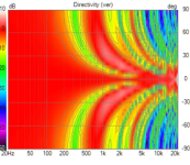
The horizontal dispersion of your line will be dictated by the TC9's native dispersion, which goes from near omnidirectional (with no baffle) at about 600Hz, narrowing to 90 degrees (-6dB @45degrees off axis, "T45" in the graphs below) at 3.15 kHz.
At 8kHz, dispersion is only 40 degrees (-6dB @20 degrees off axis).
The TC9 actually has unusually wide and smooth HF dispersion for a driver of it's diameter:
If you want wider controlled directivity you could use a HF horn (like in your EV SX200..) crossed in at around 3.15kHz above the cone drivers.
Art
Thanks Art.
You saved me a great deal of hassle with trying to shape things with wave guides.
I will short out the capacitor and re-check to see how much is causal.
If the phase shift is helping it, I'm wondering what would happen if I reversed the phase of the "outside" sets of 3 drivers just for science?
Also, the shape of the vertical seems downward sloping for some reason with a straighter more horizontal line at the upper. If I can't get that extra bit of Vertical and I'm totally stuck with the Horizontal, I think I could maybe just live with the polar as it is. It's pretty good.
Is this what you have?

Resulting in:

Let me reverse the outer sets for you:

Results in:

I don't think that would be a good idea 😉
Resulting in:
Let me reverse the outer sets for you:
Results in:
I don't think that would be a good idea 😉
Oh...... yes it is what I have.
Oops! Well... that saved me a job. Thanks for that!
I don't think I'm visualising these graphs correctly. How is distance represented?
Is this red sweet spot how it would literally look in the room if could 'see' it?
If it is, the horizontal for instance at 8kHz upwards, is more like the 40 degrees that Art described if not 30°.
Also, the Vertical doesn't open out like a trumpet at distance, unless it's a really really far distance...?
Possibly a silly question but...
Assuming the capacitor is causing (90°?) phase and that's helping the Vertical(?)....what about if I added 2 fairly pointless ones just for phase increase on the other driver banks ? (forgive all the wrong labels, I used snip and paint!)
If it is, the horizontal for instance at 8kHz upwards, is more like the 40 degrees that Art described if not 30°.
Give or take plus/minus 17.5 degrees for horizontal at 10K
Vertical still is very narrow. So yes,, it would take some distance to get a proper coverage.
At a distance of 5 meter I plotted the in-room simulation at the center of the array height and 100, 200 and 300 mm above and below it:
So you see how narrow that top end really is. +/- 10 centimeter (4 inch) you'd be fine, any more than that and it drops of fast vertically.
Even at 5 meter distance.
Thank you for modelling that for me. The simulations are so helpful and it seems, accurate!
I think before I try curving the baffle slightly, I'll Bi-amp the array thru mixers (since it's only 2 groups) and see what power and frequency shading will give me.
So.... is it reasonable to assume that Power frequency AND phase are forms of shading? or just the first 2?
Also, would that wonky phase reverse model really be so bad? Looks reasonably good to me haha.
Attachments
would that wonky phase reverse model really be so bad?
Feel free to try 😀.
There's always the Bessel array that will restore the vertical pattern to mimic that of a single driver:
This is a 9 driver Bessel array, but within a 9 driver bessel, two of them do nothing, so it only takes 7 drivers that are spaced as a 9 driver array.
To quote from the linked text:
Nine drive units will have a function ratio of A:B:C😀:E:F:G:H:I = 1:2:2:0:-2:0:2:-2:1, thus two may be omitted.
See:
Two empty spots at 85 mm and -85 mm (the zero position being the design/listening axis here)
The bessel array will have a vertical coverage that resembles the coverage of a single driver:
But it does result in a very low impedance with all those parallel connected drivers and the step up in sensitivity is pretty much gone.
So you'd have 7 drivers but it's output is only about 5/6 dB higher than a single driver with the same amount of power applied:
A single driver in comparison.
Power frequency AND phase are forms of shading?
Yes, all three can be of influence when edited separately. One could use frequency shading, by applying shelf filters instead of power shading. That's what I did with my 25 driver array, to 'bundle' the vertical output. That way I kept the higher sensitivity of the array at bass frequencies, as all drivers still worked equally hard (more or less depending on the resistance of the passive components used).
Editing phase can also alter the sum of the drivers. See the bessel array for example, where 2 drivers are connected in reversed polarity (180 degree phase shift) plus the two outer drivers only get half the amount of power (the two drivers connected in series in the schematic).
P.S. This really shows how powerful this Vituixcad tool is that kimmosto has provided. When member @nc535 started simulating TC9 line arrays with it, and I could literary see what I had seen already in my in-room measurements, I became a believer and joined the simulation fun. You can too, with that starter model I linked earlier. 😉
Last edited:
A few days I stumbled over this old thread: https://www.diyaudio.com/community/threads/yet-another-diy-line-array-project.295365/
Similar goals to yours, also looking for coverage, using a smaller driver and some in angled positions, like Bose does. May be of some use to you 😀.
Similar goals to yours, also looking for coverage, using a smaller driver and some in angled positions, like Bose does. May be of some use to you 😀.
Thanks guys. I did actually read many MANY posts before i started the build. About 30% of it went over my head. Thanks for the link. I did read Peter Pans and I actually reference it in the very first post of this thread. This was miles ago though haha.
What I need to do is re-read them all because they had information in them that will make more sense to me now.
I remember thinking that he was way happier with his than Chris661 was. If I recall, Chris found his array to be too trebly at distance.
The Array I have built is probably good enough as it is for a coffee shop gig, but my ears know the HF is not present though and I wish they didn't 😆
The Aiyima a07max in bridge mode and my EV SX100+ p1ss3s all over it. But I don't want to give up. I really like the old Rockford Fosgate subs I bought for it too. Everyone on Google and my neighbour said not to buy old foam surround drivers but they were wrong. They are mint 😎
Through my initial reading, I am aware of the Bessel Array and I think it will not go loud enough.
I will try the wonky setting because to my un-informed Eyes.... That's a pretty good spread of HF. I will obviously own up if it's rubbish.
So,...It'll be interesting to Bi-amp. It'll be Strange to hear the HF spread go UP when I turn the outer one's HF down...!!! -Or lower the volume of them.
I'm also keen to hear what a little curve will do in the baffle.
If I can't get there, it will have been fun and since I have 2 subs now I can use them underneath that weird 2 xTC9 bookshelf set up with the one reversed -remember that? Or some other TC9 project I've yet to find on here. I am not quitting yet though. I want my "Gypsy Bose" system to work!
Also, I've bought the 2nd hand 48v ebike battery to run them on when busking. It's 52V off load. Hope it doesn't smoke the caps in the Aiyima eek!
- Home
- Loudspeakers
- Multi-Way
- TC9 Array for PA system by beginner