I'm re-using a post I've written a while ago. The shape of the cabinet determines a lot of what the off-axis energy looks like.
A while ago member @fluid ran sims for a driver in a flat baffle and the same driver with a rounded enclosure, the last example in
this row (with the set back) is what I used, based on a hunch, but apparently a good one...
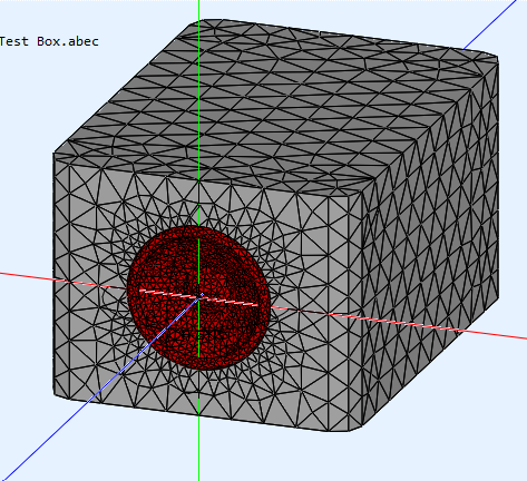
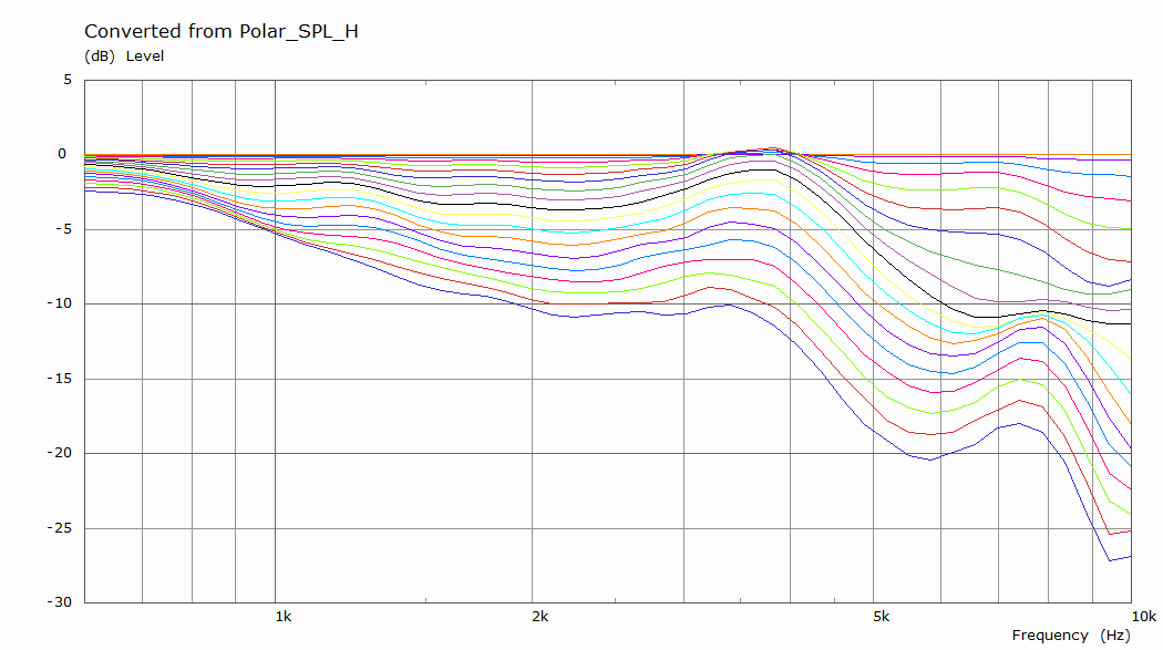
The relatively flat baffle with flush mounted driver simulation in ABEC:
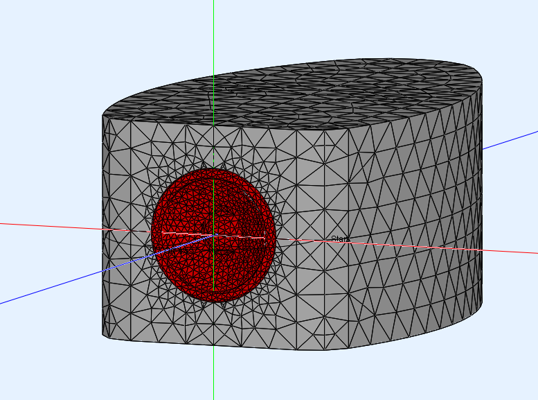
Versus the rounded enclosure with flush mounted driver:
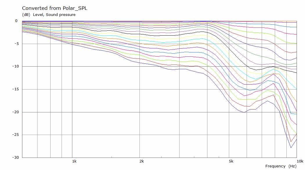
I'd say it is easy to spot differences. The first round-over used on that enclosure shape is only 25.5mm or about 1" radius. Yet the effect it has is quite obvious.
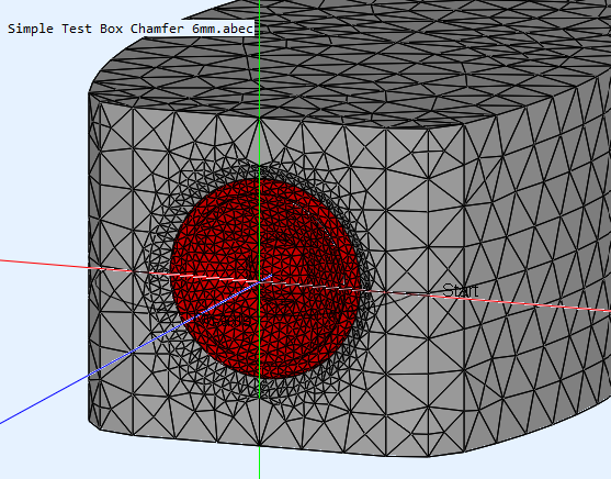
Taking this concept a step further, with the driver set back in the baffle with a small chamfer in front of the driver:
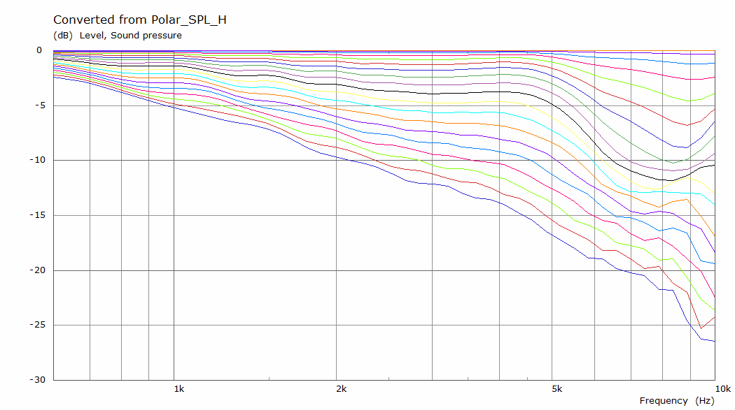
I'd say it's well worth it to try or play with things like that. Do you see how much the shape of the enclosure can determine the outcome of your project?
EQ can correct the frequency response at the listening axis, but it cannot correct an uneven off axis response. Choose wisely I'd say 😉.
On many array threads I've said: "be aware of sharp edges/ridges and parallel planes, as there the reflections are timed very similar." (*)
These sims show that it goes for enclosure shapes too. Smooth and rounded corners are not for show.
(*)- a CBT spreads out these reflections due to the delay per driver. That's one of the reasons a CBT does so well in an untreated space.
A straight array close to a side wall would benefit from first reflection treatment of that wall. As you'd get a strong reflection due to similar distances.
A while ago member @fluid ran sims for a driver in a flat baffle and the same driver with a rounded enclosure, the last example in
this row (with the set back) is what I used, based on a hunch, but apparently a good one...
The relatively flat baffle with flush mounted driver simulation in ABEC:
Versus the rounded enclosure with flush mounted driver:
I'd say it is easy to spot differences. The first round-over used on that enclosure shape is only 25.5mm or about 1" radius. Yet the effect it has is quite obvious.
Taking this concept a step further, with the driver set back in the baffle with a small chamfer in front of the driver:
I'd say it's well worth it to try or play with things like that. Do you see how much the shape of the enclosure can determine the outcome of your project?
EQ can correct the frequency response at the listening axis, but it cannot correct an uneven off axis response. Choose wisely I'd say 😉.
On many array threads I've said: "be aware of sharp edges/ridges and parallel planes, as there the reflections are timed very similar." (*)
These sims show that it goes for enclosure shapes too. Smooth and rounded corners are not for show.
(*)- a CBT spreads out these reflections due to the delay per driver. That's one of the reasons a CBT does so well in an untreated space.
A straight array close to a side wall would benefit from first reflection treatment of that wall. As you'd get a strong reflection due to similar distances.
Last edited:

Hi, it looks like you are going down the path i went.....only you are planning more channels for the arrays than i did.My thought was by using all channels dsp /active it would be able to be tuned/curved/shaded/low pass to whatever degree needed. Not quite “figure it out later” but kind of.
I built 24 driver TC9 columns with six channels of DSP/amplification. So four drivers per channel. I love the idea of a channel per driver !!!
The arrays I built used the same drivers/baffles that could mount in either a straight box or a CBT curved box. as shown below.
Even with my 6 channel limitation, I found it was pretty easy to use the straight array to mimic the CBT box, with delays and magnitude shading.
It wasn't quite as good as the CBT, but it was close. I think with 24 driver control it would have been better, but then again so would the CBT box...so dunno.
On the straight arrrays, i also played with frequency shading, and with delays to move the apparent acoustic center from the middle of the array to the top, for example. Tried concave as well, etc. It all worked very well.
You should have a blast with 24 channels and programmable DSP, other than all the wiring necessary and putting settings into the DSP lol.
I think you will learn so much, just from playing around easily, that i wouldn't spend any time trying to predict with simulations etc...
I used an open architecture processor too...Q-Sys. Those biamps look like a really inexpensive way to dip into multi-channel DSP, with great preset capacity.
It was so cool to be able to instantly switch the straight lines from a regular full normal line setup, to CBT mimic, to concave focus, to frequency shaded normal, to frequency shaded top, etc, etc.
Good luck!
Wow thats a real improvement. The rounded cabinet is probably beyond my fabrication skills atm. I was going to be happy with flush mounting and well rounded-off corners. Making the appropriate jigs (friend has a laser cutter) for all the flush trimming was added to my to-do spreadsheet early on. I can run the numbers on having CNC work done to do it layer-stacked like yours, its tempting.I'm re-using a post I've written a while ago. The shape of the cabinet determines a lot of what the off-axis energy looks like.
A while ago member @fluid ran sims for a driver in a flat baffle and the same driver with a rounded enclosure, the last example in
this row (with the set back) is what I used, based on a hunch, but apparently a good one...
The relatively flat baffle with flush mounted driver simulation in ABEC:
Versus the rounded enclosure with flush mounted driver:
I'd say it is easy to spot differences. The first round-over used on that enclosure shape is only 25.5mm or about 1" radius. Yet the effect it has is quite obvious.
Taking this concept a step further, with the driver set back in the baffle with a small chamfer in front of the driver:
I'd say it's well worth it to try or play with things like that. Do you see how much the shape of the enclosure can determine the outcome of your project?
EQ can correct the frequency response at the listening axis, but it cannot correct an uneven off axis response. Choose wisely I'd say 😉.
On many array threads I've said: "be aware of sharp edges/ridges and parallel planes, as there the reflections are timed very similar." (*)
These sims show that it goes for enclosure shapes too. Smooth and rounded corners are not for show.
(*)- a CBT spreads out these reflections due to the delay per driver. That's one of the reasons a CBT does so well in an untreated space.
A straight array close to a side wall would benefit from first reflection treatment of that wall. As you'd get a strong reflection due to similar distances.
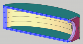
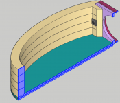
Thanks Mark, thats great to hear. The blue paint on the arrays looks really great. Do you have a cross-section you could share of what your straight box looks like internally? What did you go with for volume? The wiring is indeed scary, plan is to do use some 6-pin Phoenix connectors, and bundle them up as much as possible. Its a winter project for sure, but hoping to get cabinets done before it gets too cold outside.Hi, it looks like you are going down the path i went.....only you are planning more channels for the arrays than i did.
I built 24 driver TC9 columns with six channels of DSP/amplification. So four drivers per channel. I love the idea of a channel per driver !!!
The arrays I built used the same drivers/baffles that could mount in either a straight box or a CBT curved box. as shown below.
Even with my 6 channel limitation, I found it was pretty easy to use the straight array to mimic the CBT box, with delays and magnitude shading.
It wasn't quite as good as the CBT, but it was close. I think with 24 driver control it would have been better, but then again so would the CBT box...so dunno.
On the straight arrrays, i also played with frequency shading, and with delays to move the apparent acoustic center from the middle of the array to the top, for example. Tried concave as well, etc. It all worked very well.
You should have a blast with 24 channels and programmable DSP, other than all the wiring necessary and putting settings into the DSP lol.
I think you will learn so much, just from playing around easily, that i wouldn't spend any time trying to predict with simulations etc...
I used an open architecture processor too...Q-Sys. Those biamps look like a really inexpensive way to dip into multi-channel DSP, with great preset capacity.
It was so cool to be able to instantly switch the straight lines from a regular full normal line setup, to CBT mimic, to concave focus, to frequency shaded normal, to frequency shaded top, etc, etc.
Good luck!
View attachment 1071522
Tempting maybe, but definitely a lot of work... especially to keep it from cracking with long stacked constructions.Wow thats a real improvement. The rounded cabinet is probably beyond my fabrication skills atm. I was going to be happy with flush mounting and well rounded-off corners. Making the appropriate jigs (friend has a laser cutter) for all the flush trimming was added to my to-do spreadsheet early on. I can run the numbers on having CNC work done to do it layer-stacked like yours, its tempting.
Chamfers work well too. It's good to know how enclosure shape can influence these things though. 😉
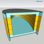
Thx! I liked the paint enough on the lines, I just put it on 3 synergies too, I have 1960 Chrysler blue out the *** haha.Thanks Mark, thats great to hear. The blue paint on the arrays looks really great. Do you have a cross-section you could share of what your straight box looks like internally? What did you go with for volume? The wiring is indeed scary, plan is to do use some 6-pin Phoenix connectors, and bundle them up as much as possible. Its a winter project for sure, but hoping to get cabinets done before it gets too cold outside.
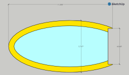
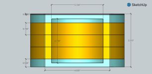
Here's a quick diagram of the internal dimensions of the straight line box. About 56L volume not accounting for a couple of small cross sectional braces, and drivers hanging in. Maybe about 2 1/4 L per driver.

I was trying to copy the Murphy Corner plans, but I had to make the dimensions a little bigger to accommodate the removable baffle I wanted, to be able to have both the staight array and CBT.
fwiw, i dont like the 'corner' array idea anymore. I think the horizontal sidewall reflections look good as mirrors in theory, but in practice create a mess. A mess that needs a lot of sidewall absorption adjacent to the lines ....
or just give up and move them out into the room, where for me they worked much better, letting the vertical line do its stuff without the lateral mess.
(Wesayso has them nailed imo.)
In figuring out what amps to use, if it were me, I would automatically assume I'm using a sub for duty below a 100Hz or so, which as you know could reduce power needed for the TC9s quite a bit. Imho, the little buggers are being asked to do too much going below 100, no matter how many of them there are...
Worked on some cabinet ideas. This one is looking like it could be a good fit. Easier to assemble, still going to be a challenge but I can see it working well. Not quite fully rounded like Wesayso showed, but better than a plain box.

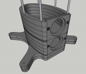
Been exploring trans-lam designs as a possibility.
The main issue becomes how do layers to give each driver its own chamber. The drivers are 3.3" tall. Using 1/2" or 3/4" MDF layers add up to 3.25", adding in a 0.06" layer of silicone rubber between sections, gets me to 3.31".
I'll add the diffusing bumps like Wesayso has in his design- still going to have the top and bottom of the chamber to contend with.
Curious if it's possible to glue these 5 layers, add in the silicone layer between modules, then stack them on threaded rods and clamp the whole setup. I saw Wesayso's cracking saga and it looks like it came down to gluing the rods in place, so def. avoiding that 🙂
Attachments
Last edited:
Another update- I have sourced another 24ch dsp box, so now I can do all drivers active. Confirmed that the various delay+attenuation settings can be scripted and be adjustable with a remote. Very much looking forward to clicking between various topologies to see whats my favorite.
Also worked out how to get a digital input to the dsp system, via cobranet, which was a challenge. Ended up finding an AES to CobraNet box, QSC Rave, and I'll be feeding it via SPDIF or a toslink to AES converter.
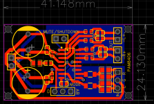
On the amplifier front I have drawn up a design with the pam8406 IC and have it populated and ready to order+assemble from JLCPCB, along with power/input+output daughter boards. The amp box with 24 modules is going to be a shitshow of jumper wires unless I decide to merge multiples onto 12ch boards, but thats out of my depth for now.
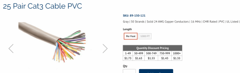
Also found some interesting 25pair, 24awg, telephone wire to potentially use from the amp to each tower with 25 pin dsub connectors on each end. I'll have to ask around if this is ok to use since its quite thin at 24awg. The run is short, (only 12' max) and its only 2W absolute max per driver.
Also worked out how to get a digital input to the dsp system, via cobranet, which was a challenge. Ended up finding an AES to CobraNet box, QSC Rave, and I'll be feeding it via SPDIF or a toslink to AES converter.
On the amplifier front I have drawn up a design with the pam8406 IC and have it populated and ready to order+assemble from JLCPCB, along with power/input+output daughter boards. The amp box with 24 modules is going to be a shitshow of jumper wires unless I decide to merge multiples onto 12ch boards, but thats out of my depth for now.
Also found some interesting 25pair, 24awg, telephone wire to potentially use from the amp to each tower with 25 pin dsub connectors on each end. I'll have to ask around if this is ok to use since its quite thin at 24awg. The run is short, (only 12' max) and its only 2W absolute max per driver.
Attachments
Last edited:
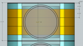
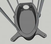
This stack looks like the best bet. Its a 1.5mm layer of taskboard, two 1/2" MDF layers, and three 3/4" MDF layers. I'm already way over on the amount of cutting I wanted to do.
Its the only arrangement I've found that gets me close to the 3.3" thickness per chamber.
Next is to explore what can be done with adding in a separately cut divider- instead of making it by milling out of portion of a teal layer.
TBD which would be less work- to do another cut with a template vs milling 1/4" out of the teal layers.
Attachments
I didn't dare use MDF as I figured it changes size/thickness due to humidity even faster than Baltic birch. The use of an alu baffle was durability if it needed service. I'm glad I chose it, even if it was a lot of work. I've assembled/disassembled it quite a few times over the years and it still is good as new.
Short stacks like you are planning should not crack, but I cannot promise anything. 🙂 If I were in your shoes, I'd make the enclosure just a hair wider and round off the shape so it transitions to the baffle in a smooth flowing line... I used a 25.5mm radius.


The wavy internal pattern was offset/different left vs right so I could stack them using only one shape and just flip over every other piece.
If anything, it makes the wall thickness vary. I don't think it does much for breaking up the internal wave front (too small), but filling it with (varying) damping materials will.
Short stacks like you are planning should not crack, but I cannot promise anything. 🙂 If I were in your shoes, I'd make the enclosure just a hair wider and round off the shape so it transitions to the baffle in a smooth flowing line... I used a 25.5mm radius.
The wavy internal pattern was offset/different left vs right so I could stack them using only one shape and just flip over every other piece.
If anything, it makes the wall thickness vary. I don't think it does much for breaking up the internal wave front (too small), but filling it with (varying) damping materials will.
I made the whole thing a bit wider to allow more space to mount the driver+baffle panels. Good call there.
So do you think its worth the effort to include the wavy pattern? I can't quite figure out how to make one that looks nice like yours.
I figure I'll line the walls with felt or carpet scrap and include a good amount of polyfill/denim towards the rear of the chamber.
Does having varying thickness of the walls improve anything?
I settled on this sandwich pattern to include the silicone/rubber layer between each chamber. It may help keep things more "isolated." and allow some room for expansion/contraction. Its available as a laser cut material from an online shop.
The 1/8" layers will probably be masonite instead of MDF. I have to look into making sure they will bond together with the MDF.
Wrt the outer baffle- I am considering doing this fastener approach. Its a lot of bolts but I don't see another way/attachment point. I'm also considering making it 24 unique sections/per driver to allow them to "float" a bit for seasonal changes.
I saw another line array using some "red glue/putty" to attach the drivers, rather than screwing them to the inner baffle. This would also free up some space for fasteners to fix the inner panel to the chamber structure.
Attachments
It's up to you what you end up doing. I don't think the wall thickness thing is a disadvantage, having a "panel" like that will not resonate as for instance a flat panel side. The enclosure with the baffle decoupling I have included in my build ended up being quite non resonant. The wavy pattern will not do much for breaking up the sound, it's just not nearly deep enough to be meaningful there. Good plan with the damping materials. People often underestimate the use of a layer of felt on the walls itself, while a couple of impedance measurements will clearly show the value of it. Absorbing material in the middle will take care of the rest.
ok. had another spare few hours today. gonna start getting templates prepped from these models. I'm getting super psyched to get cutting wood in maybe a week or two!
still need to figure out how i'm running wires to each chamber. any ideas on what wire gauge would be sufficient for this? or how to determine?
still need to figure out how i'm running wires to each chamber. any ideas on what wire gauge would be sufficient for this? or how to determine?
Attachments
Last edited:
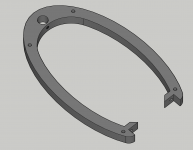
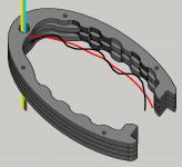
Ok I think this revision solves the wire run by going up the spine. I'll keep the other sections the same so its a minimal loss of chamber volume.Lol, I just ran the first numbers on wiring. Each tower needs 107' of wire just to get everything to the base.
10' of wire from the tower to the amps adds another 240'
so yeah, the 24awg telephone wire is the way to go for now.
It will need something to seal the hole with the wires through it- but its going to be so tiny i'm not worried.
Attachments
Don't make it too difficult to setup... wiring a line array is a tedious job already, do not make it worse 🙂.
If I were you I'd stick with simple holes between chambers that you can plug with a rubbery glue once the wire is in.
If I understand the above picture, you want to route the cable in the enclosure wall and stick out one pair of wires at each driver?
Why would you make it this hard? Just drilling a hole right before the enclosure wall between chambers would have the same function?
Don't make it too difficult to setup... wiring a line array is a tedious job already, do not make it worse 🙂.
If I were you I'd stick with simple holes between chambers that you can plug with a rubbery glue once the wire is in.
If I understand the above picture, you want to route the cable in the enclosure wall and stick out one pair of wires at each driver?
Why would you make it this hard? Just drilling a hole right before the enclosure wall between chambers would have the same function?
I appreciate the advice. You're so right - I have to remind myself that its easy to design things on the computer that would be nightmares to actually put together, all without realizing it.
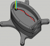
I'm not sure I understand the routing you're describing. I've included two diagrams- one with the wire inside the wall. the other with it passing through the floor. Is this what you mean? You're right thats much simpler to accomplish.
Attachments
Last edited:
- Home
- Loudspeakers
- Full Range
- TC9 active line array questions