This is probably the reason that the amp protects. Do you have a scope to check the step up circuit ?
This should be more than enough.
Confirm that all gate resistors are within tolerance (1 ohm)
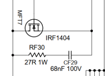
Check that during start up you have a 10% duty cycle 20KHz square wave signal at the gates of irf1404s.
Confirm that all gate resistors are within tolerance (1 ohm)
Check that during start up you have a 10% duty cycle 20KHz square wave signal at the gates of irf1404s.
Ok I will check with the 50 Mhz. Just to be clear the transistors in this amp are 180N4F6. Does that make a difference? If there is no signal what else should I check?
No, i am more concerned about the gate driver you use. Its not as strong as the original.
In my opinion, you need first to make the amp operative and then try to mod it to run into 16V
In my opinion, you need first to make the amp operative and then try to mod it to run into 16V
Of course, just wanted to let everyone know what options I had. If there is little or no signal should I change to the UCC27324 driver?
You can start by probing pins 2&4 of the 4427. If you dont have signal there, you have a faulty mcu.
Then you can check pin 6 of the 4427, you should have 12V there.
If you have the above and no output on pins 5 & 7 of the 4427, yes replace the gate driver.
I would like to post the correct frequency, it should be 25KHz, not 20KHz as i wrote earlier.
If you have drive signal to the fets but overheat, then there is not enough current drive and you should use the original part.
For this particular MCU what are the output pins that feed pins 2&4 of the driver? I want to check to make sure there is a good connection between them.
Resistors check at .8 ohms and both inputs and outputs are working on the driver until it goes into protect.
Does the output stage begin to oscillate at all before it goes into protect?
For the voltages on the MCU, how do they change before and after protect mode?
For the voltages on the MCU, how do they change before and after protect mode?
Each pair produces about 33 volts P-P before going into protect. The Pins that change on the MCU before going into protect are
Pin 16: 2.2
Pin 19: 1.5
Pin 16: 2.2
Pin 19: 1.5
- Home
- General Interest
- Car Audio
- Taramps HD3000 V2 in protect mode