I guess the problem is that I'm using a MacBook for Box Plan because it has Excel, and I'm using my PC at work for Hornresp.
Unfortunately that partly defeats the purpose of the exercise because it means you won't be able to quickly see how changes made to dimensions in the BOXPLAN workbook impact on the predicted response in Hornresp.
Agreed, but needs must.
And I only have to get this one box right, now that I am settled on a design.
And I only have to get this one box right, now that I am settled on a design.
GM
I had another look at your MLTL - you posted a .txt file of your RSS390 design - on HR and I don't really know how to interpret the schematic diagram properly, other than that the driver is sitting at the junction of S1 and S2 in a straight pipe.
Does the smaller black circle at S3 represent a vent?
So is this an MLTL in a straight pipe with a vent? Is it a straight TL because the QTS of the driver is less than 0.35?
On Brian's Diysubwoofer site which horn folding does this most closely represent?
Cheers
P
Also, Brian S, because of the problems I have with no Excel on my computer - I have to borrow the wife's laptop - and HR at work, is it possible to do the whole subwoofer design process in reverse?
That is, to get a nice TL design for my driver devised in HR, eg, for my RSS390 I have a tapered TL volume 133.3L, three to one taper, each section 80cm. Fb 27.2Hz.
And then go back to your hornfolding software, choose the appropriate boxplan, input the HR numbers and then determine the panel sizes?
Correct x3. 😉
None without figuring one out from scratch based on driver dims, vent depth.
GM
edit: no Excel loaded either, but reverse engineering from a pre-folded box due to physical size limits often makes for compromised performance when acoustically small.
None without figuring one out from scratch based on driver dims, vent depth.
GM
edit: no Excel loaded either, but reverse engineering from a pre-folded box due to physical size limits often makes for compromised performance when acoustically small.
Last edited:
One thing confuses me a bit, well many things really, but this particular one I need to ask someone about.
A vented box for the RSS390HO is meant to be around 2.7cubic feet (76L) and gives an F3 of roughly 26Hz.
Yet all of the TLs I've seen modelled or have modelled myself using this driver end up being roughly double that to achieve a similar F3.
Is that purely because of the line itself?
Also, could the RSS390HO work okay in a tapered TL? It has a Qts of 0.32 so ideally should be in a straight TL but it certainly seems to model as if it might work okay in a tapered line.
Correct.
Sure! While I have a R-O-T as to which taper to use based on experience they are not 'cast in stone' and any type of taper can be made to work, just won't necessarily be optimum WRT minimal size, F3, Fb.
Since 0.32 Qts' is near enough to 0.312 Qts', an inverse taper designed by calculating a classic BR alignment [Vb = Vas/1.44] tuned to Fs except using a vent area [Av] = Sd/3 and use the sum of the box + vent as the net volume [Vb] and its length = 34400/4/[Fs*1.56] with driver offset = L*0.33.
In 'chamber', set 'path' to L23/2, damp to 'taste' and it comes out something like this:
GM
Attachments
Last edited:
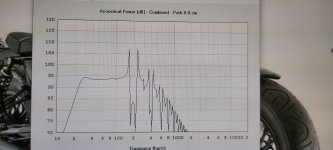
Thanks for that GM; that's a nice flat response; I'm new to HR but cannot seem to get rid of the small bump around 30Hz and a slight droop thereafter.
Still, from this point I have a tapered TL design which seems okay to me for the RSS390, and want to put it into wood. HR says box volume is 141.6L so I can design a box with this internal volume. Does that take into account the driver too, or do I need to add extra for driver volume?
The line length is 255cm and each segment is 85cm but I guess what I need to know is this: is the 85cm the length of the two dividers that create the line or does it represent the middle of the actual line itself, or is it the (internal) length of the box?
In other words, how does the 85cm segment relate to the box build?
Thanks in advance for any direction here.
Attachments
Okay, so I figure the 85cm refers to the internal length of the box, and the two internal dividers chop the 255cm line into three sections of 85cm each.
Depending on where I position the dividers creates the 3:1 taper, and I have that sorted too.
About the only thing that puzzles me is this: how long do those internal dividers need to be? The driver doesn't get in the way of any of them when it is placed one-third of the way down the line, so I just need to know roughly how far from each end they finish?
The box itself has internal dimensions of 85x44x41 for box vol of 153L. Not quite the same as the above but things changed a bit in hornresp.
Also, how does one go about accounting for the volume of a 15 inch driver? I guess it is around 10L but only a guess.
Thanks in advance for any direction anyone can offer.
One other TL query.
The box vol calculators suggested a vented box of 78.2L for the RSS390HO and Fb of 27.25 which is what I have aimed for in the HR sim of a tapered TL.
But the Fs for the driver is 21.5Hz and its Xmax is 12mm.
Should I be aiming for a figure a bit lower, around say 24Hz and making the line and box a bit bigger? At present the box is large but not huge for the space I have. Its volume is around 153L and the line is around 255cm.
I never play music at party volumes either.
Last edited:
Hmmm. Played around again with horn resp and changing where the driver sits really screws with outcome, seemingly. At the s1-s2 junction 85cm gives a nice response but at 60cm where I want the driver to be it is horrid so back to the driver at the end of a tall box I guess. Unless.there is a way around this I’m not seeing?
Thanks for that GM; that's a nice flat response; I'm new to HR but cannot seem to get rid of the small bump around 30Hz and a slight droop thereafter.
.......or do I need to add extra for driver volume?
In other words, how does the 85cm segment relate to the box build?
You're welcome!
HR doesn't account for any basic losses due to friction/whatever, hence little 'bumps', high Q spikes, etc., in sims that will go away if you enable 'MASKED' in Tools/Options.
Right, all box programs calculate NET volume [Vb], so driver, bracing, venting 'losses' must be added to it, though obviously the larger a [ML]TL's [Vb] the smaller the percentage of its loss/'shrinkage', so unless you're trying to 'squeeze' every extra cm^3 [in^3] out of the [Vb], either ignore it or just add the time honored ~10 % to it as stuffing density will compensate any reasonable excess [Vb].
Hmm, the 255 cm is the acoustic path-length, so with one end closed, don't see how any of the segments would be an acoustic 85 cm since some of it's in the bend and especially if tapered since from HR's perspective its effective axial length is the mean of a 3D cone...........
Regardless, with only vestigial math skills, I can only make a 3D drawing, cut it up into segments to figure out to fold it, with tapered converted to a specific box dimension still being no trivial pursuit, but DMB
renders it mostly moot with pattern cutting tool dimensions to load into an appropriate program such as Brian Steele's to calc the folded up variant: Schematic/File/Export/Horn Data/Rectangular Horn
GM
Thanks GM.
So I'd be better off starting the other way, with Brian Steele's horn folding software, picking the appropriate design, like MLTL, and going from there. Which is kind of where I began (but I have problems with HR not working on Mac).
At least with Brian's software I know I will get something that will probably work. Doing it the other way is much more of a gamble.
You're welcome!
Right, anytime one is stuck with a set box size/shape, the speaker alignment is ideally 'voiced' [tuned/EQ] at the location/listening position [LP] and it 'is what it is', though of course nowadays folks have a bunch of tools to work it out much better overall than my mostly pre-T/S alignments done using R-O-Ts, nomographs.
GM
Freddi
I've got a question for you.
Right back in posts 6 and 10 of this thread you (kindly) did a sim for me of Dayton's RSS390Ho15-inch driver in a simple Tapped Horn enclosure, the dimensions of which you retained, apart from width which you stretched from 13 to 16 inches to fit the driver.
The original design was from here:
Plan ! - D-20 (hz) Macro Sub ..tapped horn by moi. - Speakerplans.com Forums - Page 1
You also posted your hornresp .txt data which I have been looking at recently.
My question is this: in the HR data the schematic suggests an enclosure size of 147L, and yet when I multiply the dimensions of the box enlarged for a 16-inch diameter, I get volume of 247L or thereabouts (using dimensions of roughly 62inches by 16in by 14in).
So what am I misinterpreting here?
You need to subtract out each panel's 3/4" thickness to get the basic internal volume, then subtract out the divider's volume, the driver isn't considered in HR sims.
GM
GM
??? I get 59.5" x 16" x 12.5" = 11,900"^3 = 195 L per this little freeware: Convert for Windows – joshmadison.com
What I meant was the 100L difference between 147L of sim and 247L calculated by multiplying LxWxH of enclosure.
Another way to look at it is just calculate the extra 3" = 59.5*3*12.5 = 2,231.25^3/~36.564 L
Originally: 59.5*13*12.5 = 9668.75"^3 = 158.459 L!
158.459 L + 36.564 L = 195.023 L
OK, seems I did it right, so far.......now got to take out the divider:
54.5" x 13" x 0.75" = 531.375"^3/~8.708 L
158.459 L - ~8.708 L = ~149.751 L - 147.465 L = ~2.286 L larger = apparently the excess volume of a rectangular rendition of a round cross sectional area pipe.
195.02 L - ~8.708 L = 186.312 L - ~2.286 L = 184.026 L - 147.465 = 36.561 L - 36.564 L = so apparently somewhere in all the rounding over I 'misplaced' 0.003 L. 🙁
Regardless, close enough for me, so off 100 L seems to either be an operator and/or bad calculator/whatever, error.
GM
- Home
- Loudspeakers
- Subwoofers
- Tapped sub box/Karlson design for RSS390HO?