Very good, thanks for that. Reading the instructions it now makes a whole lot more sense!
I'd forgotten that they were at the bottom of the Boxplans.
I'd forgotten that they were at the bottom of the Boxplans.
Last edited:
Hi Brian
Try, and another epic fail using the RSS390 in the MLTL BOX Plan. I tried to follow your 11 steps but I think I must be missing out inputting something because I don't what may be a critical value? Im just using what numbers I can glean from the PE website.
When I input the box dimensions in the design area, the driver is part sitting in the box, part out. It is sited way too low.
I tried messing around with different box dimensions but I never got the driver to fit inside the box so never got to optimise the box. The piece of wood that is meant to define the transmission line is tiny and smashed up against the back of the driver!
So it's a mess.
Thanks GM.
Im such a noob I don't even know what to do with the txt file.
But I guess I just plug it into hornresp?
Im such a noob I don't even know what to do with the txt file.
But I guess I just plug it into hornresp?
Correct, DL it into the HR IMPORT folder, then in HR, click on FILE/IMPORT/HR Record, find it in the menu, double click on it and it auto loads as a new file all ready to use/save/whatever. View the sim with stuffing in the LS Wizard.
GM
GM
Brian
I had another thought about what’s going wrong. I’m simply overwriting your figures in the MLTL Box plan. But I failed to clear out the boxes I cannot fill in so perhaps there is still data there for your driver that is mucking up results for my driver?
I had another thought about what’s going wrong. I’m simply overwriting your figures in the MLTL Box plan. But I failed to clear out the boxes I cannot fill in so perhaps there is still data there for your driver that is mucking up results for my driver?
Hi GM
I managed to import the file and open it on HR and the power response looks broad enough for my purposes, and it seems to dig pretty low too.
Is the design itself (I note that it is 144L) similar to that of the Boombox?
For my purposes the only real design issue I have is that the box has to be no more than 17in wide. Height and depth not really an issue, though if I could keep the enclosure from not looking like a coffin that would be an advantage aesthetically (says she).

Thanks Brian. Appreciate it.
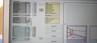
Where did you get that 250cm3 figure from? And what would you advise re vent size?
Also, the 195L gross vs 145L net volume enclosure figures. What do they signify or mean exactly?
Finally, 38.8cm is the frame width, and 39.4cm is the baffle width. Is that cutting it a bit fine or is that essentially plenty enough for the driver to fit?
Thanks again for taking the time.
Peter
And also I can account for all the panels okay but am confused by the panel offset.
Im guessing that in this instance it isn't necessary?
Im guessing that in this instance it isn't necessary?
Brian, I have one other minor query regarding the MLTL build for the RSS390HO.
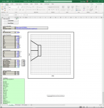
How exactly do I determine where the driver and panel E are positioned in the box?
I take it I just refer to the grids on the image. So panel E starts one quarter of the way up and extends to one half the way up the box, while the driver starts one sixteenth of the way down from the inside of the top panel (and six sixtheenths up from the bottom), correct?
Cheers
Peter
Check the "Guides" sheet in the workbook. Basically you mark off the guidelines as indicated on a side panel, and use those guidelines to position the other panels.
Note that what I gave you should be considered a starting point. You should experiment with adding stuffing to the sim, resizing the box, etc. until you end up with something that best fits your needs.
Note that what I gave you should be considered a starting point. You should experiment with adding stuffing to the sim, resizing the box, etc. until you end up with something that best fits your needs.
Brian
A couple of queries after playing with the BOX Plan MLTL programme yesterday.
I'm not sure how to go about checking the power response and also the effect of fibrefill
in the enclosure.
Do I need to import a txt file into hornresp?
I just couldn't seem to work out how to do that on the Excel software, ie, make a txt file of the data.
Each time I tried to Export a file I was denied (something about bug end?).
Or can the power response and the effect of fibrefill all be done in your Box Plan programme (I don't believe so but am generally wrong and incompetent with new software).
Any direction here would be appreciated.
What I should probably also do is sim how the two 10-inch RSS265HO-44 drivers would look in a slightly tall box of otherwise similar design and dimensions.
You need to use the workbook's "Export" feature to export the Hornresp sim that corresponds to what you've designed using the workbook. Make sure that the export directory is the same as Hornresp's import directory (usually c:\hornresp\import). Once you've done that, use Hornresp's import feature to import the sim. You can look at the results using Hornresp's "Loudspeaker Wizard" feature. You can also make adjustments in the workbook, export the results, and press "F6" in Hornresp to update Loudspeaker Wizard with the adjusted sim.
Brian
Your explanation was helpful but I couldn't seem to make the 'export' button work.
It kept coming up with a dialog box saying 'debug'
Im guessing that the copied line below from the Design page in the workbook is the relevant one you are talking about, correct?
Would you mind precisely telling me what it should read? Thx for this.
Export Filename =I:\Users\Brian.Steele\OneDrive\Hornresp\Import\peterl20 Jul.TXT
Comment = BOXPLAN-MLTL 2.5 - 2020-07-20 13:05:26
Would you mind precisely telling me what it should read?
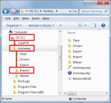
As Brian says, the file exported from the BOXPLAN workbook needs to be saved into the Hornresp Import folder, which is located directly beneath the Hornresp folder. If Hornresp has been installed as recommended in the Readme file, then Export Filename = C:\Hornresp\Import\YOURFILENAME.TXT. If Hornresp has been installed somewhere else, then that path must be used instead.
Comment = Your comment
Attachments
Thanks David and Brian.
I guess the problem is that I'm using a MacBook for Box Plan because it has Excel, and I'm using my PC at work for Hornresp.
So I guess I will need to save a file and send it to work to make this happen.
A pity I can't run them both on the same MacBook.
I guess the problem is that I'm using a MacBook for Box Plan because it has Excel, and I'm using my PC at work for Hornresp.
So I guess I will need to save a file and send it to work to make this happen.
A pity I can't run them both on the same MacBook.
- Home
- Loudspeakers
- Subwoofers
- Tapped sub box/Karlson design for RSS390HO?