John/Patrick,
Have you ever considered a full height, off-center baffle like the sketch attached? The advantage is that it should be fairly easy to accommodate a large port in a design with a relatively small front chamber. The math to calculate the sectional volumes is straightforward (although I cheated – just found an equation out there on the web). The only downside I see is the close proximity of the port to the enclosure walls. I understand this may lower the tuning frequency, but I assume that could be corrected experimentally. Are there other downsides? Also, how do you inject the fill between the two layers for tall designs - through holes in the outer wall?
- Doug
An externally hosted image should be here but it was not working when we last tested it.
DougSmith said:John/Patrick,
Have you ever considered a full height, off-center baffle like the sketch attached? The advantage is that it should be fairly easy to accommodate a large port in a design with a relatively small front chamber. The math to calculate the sectional volumes is straightforward (although I cheated – just found an equation out there on the web). The only downside I see is the close proximity of the port to the enclosure walls. I understand this may lower the tuning frequency, but I assume that could be corrected experimentally. Are there other downsides? Also, how do you inject the fill between the two layers for tall designs - through holes in the outer wall?
- Doug
An externally hosted image should be here but it was not working when we last tested it.
I couldn't find an equation for that. Could you post the URL you used?
Believe it or not, I figured out the area for the tapped horn in this thread by "digitizing" the cross section on graph paper basically. I'm sure there's a formula for calculating a portion of a circle, but I couldn't find one.
Of course it's easy to calculate a section of the circle if that section crosses the midpoint, but in the example you posted, it does not.
Mark Seaton said:
Hi Earl,
The tapped horn is most like a 6th order bandpass, and most analogous to a vented box vs. a transmission line comparison. I've been designing plenty of 4th and 6th order bandpasses lately, and there are many similarities and a few differences which can of course work for or against you. For the rest reading along, the important difference lies in the significant distance/lengths involved related to the design vs. the operating bandwidth, so you have to account for 1/4 wave resonances and other effects which again can be problematic or beneficial.
The comparison of a 4th order bandpass to a 6th order makes for a reasonably parallel comparison of a horn and a tapped horn. As with most higher order systems including more variables, they are also easier to screw up, requiring a little more fine tuning or accuracy and completeness in the modeled parameters.
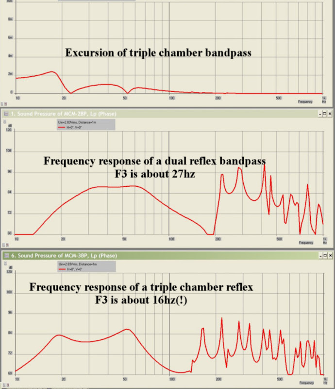
I threw together a model for a triple chamber subwoofer in Akabak yesterday.
I'm not 110% sure that this is correct; I really put it together quickly. It seems like there should be three excursion minimums, as there are three tuning points. (I'm only seeing two.)
Here's what the box looks like:
An externally hosted image should be here but it was not working when we last tested it.
Here's a graph from Akabak:
System 'S1'
|DATA EXPORTED FROM HORNRESP - RESONANCES NOT MASKED
|COMMENT: MCM 55-2421 in a single reflex bandpass
|========================================================================================================
|REQUIRED AKABAK SETTINGS:
|File > Preferences > Physical system constants:
|Sound velocity c = 344m/s
|Medium density rho = 1.205kg/m3
|Sum > Acoustic power:
|Frequency range = 10Hz to 20kHz
|Points = 533
|Input voltage = 2.83V rms
|Integration = 2Pi-sr
|Integration steps = 1 degree ... 1 degree
|Integration method = Cross
|========================================================================================================
Def_Const |Hornresp Input Parameter Values
{
|Length, area and volume values converted to metres, square metres and cubic metres:
Rg = 5.00e-0; |Amplifier output resistance (ohms)
S1 = 81.00e-4; |Horn segment 1 throat area (sq cm)
S2 = 81.01e-4; |Horn segment 1 mouth area and horn segment 2 throat area (sq cm)
S3 = 81.02e-4; |Horn segment 2 mouth area and horn segment 3 throat area (sq cm)
S4 = 81.05e-4; |Horn segment 3 mouth area (sq cm)
L12 = 20.00e-2; |Horn segment 1 axial length (cm)
L23 = 20.00e-2; |Horn segment 2 axial length (cm)
L34 = 20.00e-2; |Horn segment 3 axial length (cm)
Vrc = 34.10e-3; |Rear chamber volume (litres)
Lrc = 75.00e-2; |Rear chamber average length (cm)
Vfc = 34.10e-3; |Front chamber volume (litres)
Lfc = 75.00e-2; |Front chamber average length (cm)
Ap = 45.59e-4; |Chamber port cross-sectional area (sq cm)
Lpt = 60.00e-2; |Chamber port tube length (cm)
Vtc = 14160.00e-6; |Throat chamber volume (cc)
Atc = 325.57e-4; |Throat chamber cross-sectional area (sq cm)
Ata = 81.05e-4; |Throat port cross-sectional area (sq cm)
Tpt = 100.00e-2; |Throat port tube length (cm)
|Parameter Conversions:
Sd = 220.00e-4; |Diaphragm area (sq cm)
Arc = Vrc / Lrc;
Ltc = Vtc / Atc;
}
|========================================================================================================
|Network node numbers for this horn-loaded vented-box system:
| 0-Voltage-1-Resistance-2
| |
|Radiator(1)-3-Port-4-Chamber-5-Driver-6-Chamber-8-Segment-9-Segment-10-Segment-11-Radiator(2)
| 3-Port-4-Chamber-5-Driver-6-Chamber-7-Port
| |
| --------------------------------------------------------------------12-Chamber-8-Segment-9-Segment-10-Segment-11-Radiator(1)
|========================================================================================================
Def_Driver 'Driver'
Sd=220.00cm2
Bl=14.61Tm
Cms=3.46E-04m/N
Rms=1.21Ns/m
fs=30.9996Hz |Mmd = 74.30g not recognised by AkAbak, fs calculated and used instead
Le=2.42mH
Re=3.40ohm
ExpoLe=1
System 'System'
Resistor 'Amplifier Rg'
Node=1=2
R={Rg}
Driver Def='Driver''Driver'
Node=2=0=5=6
Duct 'Rear Port'
Node=4=3=12
SD={Ap}
Len={Lpt}
Visc=0
Duct 'Rear chamber'
Node=4=5
SD={Arc}
Len={Lrc}
Visc=0
Duct 'Throat chamber'
Node=6=7
SD={Atc}
Len={Ltc}
Visc=0
Duct 'Throat Port'
Node=7=12
SD={Ata}
Len={Tpt}
Visc=0
Duct 'Front chamber'
Node=12=8
SD={Vfc}
Len={Lfc}
Visc=0
Waveguide 'Horn segment 1'
Node=8=9
STh={S1}
SMo={S2}
Len={L12}
Conical
Waveguide 'Horn segment 2'
Node=9=10
STh={S2}
SMo={S3}
Len={L23}
Conical
Waveguide 'Horn segment 3'
Node=10=11
STh={S3}
SMo={S4}
Len={L34}
Conical
Radiator 'Horn mouth'
Node=11
SD={S4}
Label=2
There's a mistake in the model from post 244 and 245. I fixed it.
Here's a pic of a dual reflex versus a triple-reflex:
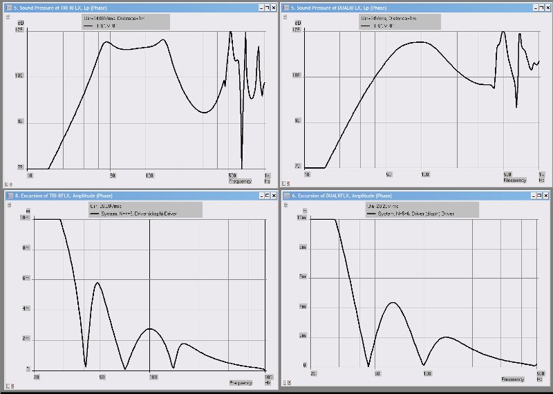
The pic with the flatter response and the wider bandwidth is the triple reflex.
Here's the model, using a P-Audio SN12MB.
System 'S1'
|========================================================================================================
|REQUIRED AKABAK SETTINGS:
|File > Preferences > Physical system constants:
|Sound velocity c = 344m/s
|Medium density rho = 1.205kg/m3
|Sum > Acoustic power:
|Frequency range = 10Hz to 20kHz
|Points = 533
|Input voltage = 2.83V rms
|Integration = 2Pi-sr
|Integration steps = 1 degree ... 1 degree
|Integration method = Cross
|========================================================================================================
Def_Const |Hornresp Input Parameter Values
{
|Length, area and volume values converted to metres, square metres and cubic metres:
Rg = 0.01e-0; |Amplifier output resistance (ohms)
S1 = 182.37e-4; |Horn segment 1 throat area (sq cm)
S2 = 364.74e-4; |Horn segment 1 mouth area and horn segment 2 throat area (sq cm)
S3 = 547.11e-4; |Horn segment 2 mouth area and horn segment 3 throat area (sq cm)
S4 = 729.48e-4; |Horn segment 3 mouth area (sq cm)
L12 = 8.00e-2; |Horn segment 1 axial length (cm)
L23 = 8.00e-2; |Horn segment 2 axial length (cm)
L34 = 8.00e-2; |Horn segment 3 axial length (cm)
Vrc = 28.32e-3; |Rear chamber volume (litres)
Lrc = 25.4e-2; |Rear chamber average length (cm)
Ap = 81.05e-4; |Rear port cross-sectional area (sq cm)
Lpt = 34.92e-2; |Rear port tube length (cm)
Vtc = 18240.00e-6; |Front chamber volume (cc)
Atc = 550.00e-4; |Front chamber cross-sectional area (sq cm)
Ata = 182.35e-4; |Front port cross-sectional area (sq cm)
Tpt = 18.00e-2; |Front port tube length (cm)
V3c = 56.32e-3; |Third chamber volume (litres)
L3c = 30.0e-2; |Third chamber average length (cm)
|Parameter Conversions:
Sd = 550.00e-4; |Diaphragm area (sq cm)
Arc = Vrc / Lrc;
Ltc = Vtc / Atc;
A3c = V3c / L3c;
}
|========================================================================================================
|Network node numbers for this horn-loaded vented-box system:
|0-Voltage-1-Resistance-2
| |
| 3-Chamber-4-Driver-5-Chamber-7-Port-12-Chamber-8-Segment-9-Segment-10-Segment-11-Radiator(1)
| |
| --------Port--------------------------
|========================================================================================================
Def_Driver 'Driver'
Sd=550.00cm2
Bl=20.12Tm
Cms=1.0E-04m/N
Rms=5.66Ns/m
fs=53.83Hz |Mmd = 74.30g not recognised by AkAbak, fs calculated and used instead
Le=0.67mH
Re=5.23ohm
ExpoLe=1
System 'System'
Resistor 'Amplifier Rg'
Node=1=2
R={Rg}
Driver Def='Driver''Driver'
Node=2=0=4=5
Duct 'Rear Port'
|Node=4=3=12
Node=3=12
SD={Ap}
Len={Lpt}
Visc=0
Duct 'Rear chamber'
Node=4=3
SD={Arc}
Len={Lrc}
Visc=0
Duct 'Front chamber'
Node=5=7
SD={Atc}
Len={Ltc}
Visc=0
Duct 'Front Port'
Node=7=12
SD={Ata}
Len={Tpt}
Visc=0
Duct 'Third chamber'
Node=12=8
SD={A3c}
Len={L3c}
Visc=0
Waveguide 'Horn segment 1'
Node=8=9
STh={S1}
SMo={S2}
Len={L12}
Conical
Waveguide 'Horn segment 2'
Node=9=10
STh={S2}
SMo={S3}
Len={L23}
Conical
Waveguide 'Horn segment 3'
Node=10=11
STh={S3}
SMo={S4}
Len={L34}
Conical
Radiator 'Horn mouth'
Node=11
SD={S4}
Here's a pic of a dual reflex versus a triple-reflex:
The pic with the flatter response and the wider bandwidth is the triple reflex.
Here's the model, using a P-Audio SN12MB.
System 'S1'
|========================================================================================================
|REQUIRED AKABAK SETTINGS:
|File > Preferences > Physical system constants:
|Sound velocity c = 344m/s
|Medium density rho = 1.205kg/m3
|Sum > Acoustic power:
|Frequency range = 10Hz to 20kHz
|Points = 533
|Input voltage = 2.83V rms
|Integration = 2Pi-sr
|Integration steps = 1 degree ... 1 degree
|Integration method = Cross
|========================================================================================================
Def_Const |Hornresp Input Parameter Values
{
|Length, area and volume values converted to metres, square metres and cubic metres:
Rg = 0.01e-0; |Amplifier output resistance (ohms)
S1 = 182.37e-4; |Horn segment 1 throat area (sq cm)
S2 = 364.74e-4; |Horn segment 1 mouth area and horn segment 2 throat area (sq cm)
S3 = 547.11e-4; |Horn segment 2 mouth area and horn segment 3 throat area (sq cm)
S4 = 729.48e-4; |Horn segment 3 mouth area (sq cm)
L12 = 8.00e-2; |Horn segment 1 axial length (cm)
L23 = 8.00e-2; |Horn segment 2 axial length (cm)
L34 = 8.00e-2; |Horn segment 3 axial length (cm)
Vrc = 28.32e-3; |Rear chamber volume (litres)
Lrc = 25.4e-2; |Rear chamber average length (cm)
Ap = 81.05e-4; |Rear port cross-sectional area (sq cm)
Lpt = 34.92e-2; |Rear port tube length (cm)
Vtc = 18240.00e-6; |Front chamber volume (cc)
Atc = 550.00e-4; |Front chamber cross-sectional area (sq cm)
Ata = 182.35e-4; |Front port cross-sectional area (sq cm)
Tpt = 18.00e-2; |Front port tube length (cm)
V3c = 56.32e-3; |Third chamber volume (litres)
L3c = 30.0e-2; |Third chamber average length (cm)
|Parameter Conversions:
Sd = 550.00e-4; |Diaphragm area (sq cm)
Arc = Vrc / Lrc;
Ltc = Vtc / Atc;
A3c = V3c / L3c;
}
|========================================================================================================
|Network node numbers for this horn-loaded vented-box system:
|0-Voltage-1-Resistance-2
| |
| 3-Chamber-4-Driver-5-Chamber-7-Port-12-Chamber-8-Segment-9-Segment-10-Segment-11-Radiator(1)
| |
| --------Port--------------------------
|========================================================================================================
Def_Driver 'Driver'
Sd=550.00cm2
Bl=20.12Tm
Cms=1.0E-04m/N
Rms=5.66Ns/m
fs=53.83Hz |Mmd = 74.30g not recognised by AkAbak, fs calculated and used instead
Le=0.67mH
Re=5.23ohm
ExpoLe=1
System 'System'
Resistor 'Amplifier Rg'
Node=1=2
R={Rg}
Driver Def='Driver''Driver'
Node=2=0=4=5
Duct 'Rear Port'
|Node=4=3=12
Node=3=12
SD={Ap}
Len={Lpt}
Visc=0
Duct 'Rear chamber'
Node=4=3
SD={Arc}
Len={Lrc}
Visc=0
Duct 'Front chamber'
Node=5=7
SD={Atc}
Len={Ltc}
Visc=0
Duct 'Front Port'
Node=7=12
SD={Ata}
Len={Tpt}
Visc=0
Duct 'Third chamber'
Node=12=8
SD={A3c}
Len={L3c}
Visc=0
Waveguide 'Horn segment 1'
Node=8=9
STh={S1}
SMo={S2}
Len={L12}
Conical
Waveguide 'Horn segment 2'
Node=9=10
STh={S2}
SMo={S3}
Len={L23}
Conical
Waveguide 'Horn segment 3'
Node=10=11
STh={S3}
SMo={S4}
Len={L34}
Conical
Radiator 'Horn mouth'
Node=11
SD={S4}
How will this 12-inch P-Audio driver go in the large 2.2meter (18Hz?) tapped horn?
http://www.cannonsound.com.au/p/577280/paudio-c12-300mb-300-watt-12-inch-mid-bass.html
Any comparable driver I should consider?
Regards.
Andrew.
http://www.cannonsound.com.au/p/577280/paudio-c12-300mb-300-watt-12-inch-mid-bass.html
Any comparable driver I should consider?
Regards.
Andrew.
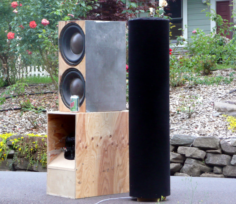
Patrick Bateman said:Here's the details on the bandpass sub. It's stupid easy to build. I put two of them together in under six hours with nothing more than a jigsaw, a drill, and a handsaw. One sub is about 80% complete, the other is about 50%. It is easily 10x easier to assemble than the tapped horn, which is MUCH more difficult to build than I realized.
First off, the bandpass sub requires modifications to the MCM 55-2421 woofer. In a nutshell, I add mass to lower the FS and raise the QMS, then I add a resistor to raise the QES. These modifications make it work much better in a single-reflex bandpass.
The front chamber of the sub is 15.8 liters.
The rear chamber of the sub is 34.1 liters.
The front chamber has a vent which measures 22" in length and 3" in diameter. The volume of the vent is 212."
The rear chamber is sealed; the woofer is in the rear chamber, and takes up 113".
The total volume of the front chamber, including the port, is 1176" (964" + 212").
The total volume of the rear chamber is 2194".
I juggled all the numbers so that this sub needs exactly ONE sonotube 😀
The rear chamber is 31" in length; the front chamber is 17" in length. Note that you'll have to use a 180 degree turn to fit a 22" port into a chamber that's 17" long. No, I didn't factor in the volume of the front cap and the end cap, but it certainly wouldn't make more than a half DB difference 😛
Here's a pic of the subwoofer. (It's the one that's in black carpet.)
Sound quality ??
Hello Patrick,
I read your entire thread today and it was really informative.
Very useful comparisons of efficiency and enclosure volumes.
However there was no comparison of the sound quality of the closed cabinet enclosures: sealed and Hemholtz (including BP, BR) versus the quarter WL waveguide based open enclosures (including TL, tapped horns). My attempt for a DIY subwoofer was to get better musical sound quality in terms of transient response and less coloration compared to commonly available commercial models all of which are either sealed or BR or rarely BP. Although a sealed SW is flaunted to have the best sound quality, a DIY version would at best have the same sound quality as a good commercial sealed model.
In this quest I have made prototypes of open baffle, H-frame, mass loaded uniform TL and open TL. Inspired by your dummies design, for just 'proof of concept' I put together today a 6'x14" sonotube tapped horn using 2 generic 8" drivers from PE with Qts=1.08 and Fs=45 that cost less than 5$ each. Despite not having done a sim on hornresp, the results are quite impressive !! Sound quality is better compared to my sealed commercial SW that costs 10 times more.
You seem to be the most hands-on experienced person around having done both BP and TH models. I agree that for in-home HT use, multiple BP is a reasonable choice. But which SW model (closed enclosure v/s waveguide based TL/TH) would you prefer for music with electrostatic/planar speakers requiring "fast" bass with minimum coloration ? I have dismissed dipoles for now given high IM distortion occuring from excessive cone excursion after the essential 12dB/octave bass-boost.
Thanks for starting this valuable thread.
Joy.
25 pages and only two seperate replies with photos showing these tubes and a ton of computer generated graphs. So much for the topic title...where is the for dummies part come in? I just want simple music at good volume(SPL) without needing a degree in advanced engineering!
Got any simple diagrams with measurements? I can build anything....
Scott (keep it simple for us dummies) B
Got any simple diagrams with measurements? I can build anything....
Scott (keep it simple for us dummies) B
- Status
- Not open for further replies.
- Home
- Loudspeakers
- Subwoofers
- Tapped Horn for Dummies