Elvee,
I'm referring to the schematic from post #95.
R14 is 4k7, which makes it run very hot at almost 2W (with 50V rails).
Do we have an option to increase it's value, and lower the current (currently 17mA)?
Not sure if current this high, is needed by Q8?
The change would affect idle current of the OS, so if R14 is changed, something else also has to change..
No, such a low value is not required, it's a remnant of the original, low-voltage prototype. You could inspire yourself from the TandyMOS, where this resistor is tied to GND, not V+, and in my prototype I used a 5K6, and added a green LED in series.
You could also add D14 of the TandyMOS to limit the inverse Vbe voltage of the drive transistor.
The change in quiescent current will be minimal, but if you want to adjust it, you can act on R13, or the ratio of R17 to R10
You could also add D14 of the TandyMOS to limit the inverse Vbe voltage of the drive transistor.
The change in quiescent current will be minimal, but if you want to adjust it, you can act on R13, or the ratio of R17 to R10

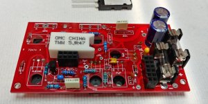
I'm back from vacations (including 4 days in Brussels, Brugge and Ostende, which is fitting with Belgian-rooted amp 🙂, and working on the PCB assembly, which just arrived few days ago.
Planning to start testing the build early next week.
Planning to start testing the build early next week.
Ya, Q6 emitter is going to max out about 0.65/150 = 4.3mA. For zero collector current that would be 100/4.3mA = 23K, but maybe you don't need to maintain 4.3mA so if we allow min gain of 10 then R14 could be 230K, or 100K from 50V (ground). This will reduce the diode drops but that is easy to compensate for.
I hope you enjoyed your stay, and will similarly enjoy your build!I'm back from vacations (including 4 days in Brussels, Brugge and Ostende, which is fitting with Belgian-rooted amp 🙂, and working on the PCB assembly, which just arrived few days ago.
Planning to start testing the build early next week.
It looks promising, but I don't know how the 0.47 ohm will behave: it is probably inductive, and may have unexpected effects. In my build, I used two power-film 1 ohm paralleled (for compactness, mostly, I didn't consider the parasitic effects), but I had to replace the fast diode with an ultra-fast one, to get rid of inductive-like effects.
We will see how it works out. If you find yourself in trouble, it will always be possible to find a workaround
We will see how it works out. If you find yourself in trouble, it will always be possible to find a workaround
I have 3W 0.22 ohm metal film resistors i could use in the sequence..
This 5W one will definitely be inductive..
This 5W one will definitely be inductive..
Fast reaction!
I do not even know if it is actually required, but it is probably the safest option.
I do not even know if it is actually required, but it is probably the safest option.
The first attempt to power the board (with plugged input/vas module) ended up with smoke from yet unidentified part.
When testing without input/vas module (bases of Q5/Q9 grounded) everything (including all voltages) looks normal.
Need to try to find out what exactly happened..
When testing without input/vas module (bases of Q5/Q9 grounded) everything (including all voltages) looks normal.
Need to try to find out what exactly happened..
Which VAS did you use?
Have you tried to test the tandem OP in isolation, with a low-impedance generator directly connected to its input?
Have you tried to test the tandem OP in isolation, with a low-impedance generator directly connected to its input?
Which VAS did you use?
That could be a problem, I used different input/vas board that the one used in the sim (I used this vas instead..)
Will retry with exactly the same module, as in the sim, assuming nothing really burned yet.
No, only tried with Q5/Q9 grounded. Not sure if my generator is low-impedance....Have you tried to test the tandem OP in isolation, with a low-impedance generator directly connected to its input?
All the voltages were matching the simulated voltages in this case.
Had some time to try again. Testing amp built from schematic from the post #73.
PSU has current limit set to 10mA.
C25 is omitted on the PCB.
1) with bases of Q5/Q9 grounded, tried to connect sinus wave generator to the base of Q10.
Ranging input Vpp of the input from 0 to 12V, I can see on the output only approx 500mVpp
No oscillations as far as I can tell.
Idle current shown by the PSU (without any signal) is about 1-2mA
That's wrong - according to the sim (with grounded Q5/Q9), idle current of the OS should be over 70mA).
2) tried connecting the input/vas module again. This time the same module used in the sim (like in post #73).
Current limit set to 10mA again.
Oscilloscope shows random oscillations, and R10 gets immediately very hot (but not damaged).
Voltage on Q11 Emitter is about -8V (normally, without VAS it's -41V, just like in the sim).
Voltage on Q11 Collector is about 18V (normally, without VAS it's 37V, just like in the sim).
All these voltages and PSU current strongly fluctuate, and oscilloscope shows chaotic oscillations.
There is something totally wrong somewhere: R15 alone should consume ~10 times more than 1 or 2mA.
Injecting a signal at the base of Q10 with Q5 and 9 grounded will limit the signal to ~1.2Vpp.
Ideally, the signal should be injected from the junction of D7 and D8, from a low impedance source or with the upstream circuit disabled.
The tandem OP must be working in isolation before it is connected to the rest of the amplifier, and this means that the DC conditions have to be right.
The best troubleshooting method is probably to compare the voltages on the nodes of the real and simulated amplifiers.
This has to yield results, because the tandem engine works in sim, and reality: I have built it, and it is possible to infer the operation from mere inspection.
That's valid for DC only; once the loop is closed, instabilities may show up, but that's another story: everything downstream of Q5/Q9 needs to operate as an ideal unity gain buffer, having a rather substantial quiescent current.
Once that aspect is fixed, you may progress further
The tandem OP must be working in isolation before it is connected to the rest of the amplifier, and this means that the DC conditions have to be right.
The best troubleshooting method is probably to compare the voltages on the nodes of the real and simulated amplifiers.
This I've already done in the 1st round of testing:
All the voltages were matching the simulated voltages in this case.
That was with Q5/Q9 grounded.
I'll try to investigate what's wrong with idle current (without input/VAS).
There is an obvious anomaly:
The voltage on the base of Q15 is -41.7V, but the voltage on its emitter is higher, -38.67V, which normally impossible.
The voltage on the base of Q6 is -41.7V, only 0.3V hiigher than the emitter voltage, which is insufficient, yet looking at the voltages across R17, the collector current is 6mA, enough to steal all the current from R5.
There seems to be a problem in the region of Q6 and Q15, or the associated resistors
- Home
- Amplifiers
- Solid State
- Tandem-based amplifiers