I'm trying to run sims of your latest Tandem with higher rails. Whiles sinus waves behave very well, with minimal distortions, the square waves are still a mess. I'll continue on it...
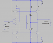
For your amusement: a CFP diamond buffer with regen bias that likes to run ~class-B. The output BE junctions are used as the current sense diodes. Note the 2 Ohm load, but of course 4 or 8 gives better THD. There may be thermal issues, but it is a variation on "auto-bias". There is more going on here than I completely understand, including the importance of the cross-coupling cap. Because the bias feedback depends on the OP current, startup resistors are required.
Attachments
Without the various capacitors, the latest version behaves atrociously on square waves, but with the right values in the right places, it becomes perfectly clean, as the oscillogram attests.I'm trying to run sims of your latest Tandem with higher rails. Whiles sinus waves behave very well, with minimal distortions, the square waves are still a mess. I'll continue on it...
Interesting development, and compact too. The THD is somewhat disappointing though, especially when compared to the real figure of the "historic" circuit.For your amusement: a CFP diamond buffer with regen bias that likes to run ~class-B. The output BE junctions are used as the current sense diodes. Note the 2 Ohm load, but of course 4 or 8 gives better THD. There may be thermal issues, but it is a variation on "auto-bias". There is more going on here than I completely understand, including the importance of the cross-coupling cap. Because the bias feedback depends on the OP current, startup resistors are required.
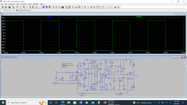
The sim seems to be completely lost and incoherent: I have probed the voltages at two nodes, first the emitter of Q10 in red: the peak voltage reaches ~90V with a supply of 50V, and there is no inductor in the circuit or a differentiating capacitor that could explain such a spike. It comes out of nowhere.
The second waveform (green) is the anode of D1: it goes 20V more negative than the -50V, again without a plausible reason.
With the sim behaving so badly, the end result when the GNFB loop is closed is a total mess unsurprisingly.
I have no idea where to begin to investigate. I tested and tweaked all my circuits in reality, because I had noticed that the sim gave incoherent results
I have tested the sim with an integrated darlington, and it has the same physically impossible behaviour:

Since it is a quasi-exact reproduction of my physical build (except for transistor types), it probably means that the unmodified circuit would work in reality.
Something I can do is to replace the TIP122 with a discrete combo, and see if the behaviour remains the same. This will only test the tandem OP part, not the frontend, but in sim the OP misbehaves even with the signal source directly feeding it, thus the test should be relatively valid. The supply voltage will be somewhat lower, but this should have no major effect.
Attachments
I tried sims with Tip122 darlington with the same results. I also tried different transistors (MJ/BD,KSA/KSC,MJL,...) - the circuit is forgiving in the sense that sinus waves most of the time work perfectly, and squares don't....
I also played with different NFB compensation, and different RC values in the OS..
I also played with different NFB compensation, and different RC values in the OS..
It would be interesting to see the sim result with another simulator than LTspice. I don't think it would change a lot, because the spice system has to adhere to the same basic rules to be able to use the same models, but each soft certainly has its own quirks and peculiarities. Settings probably play a role too, but I don't know which ones would influence the outcome.
If someone can try to simulate the output section with another soft, it would be interesting.
Anyway, I am going to make the physical test with a discrete darlington, but considering the evidence available so far, my bet is that it will work, maybe with some values adjustments.
If someone can try to simulate the output section with another soft, it would be interesting.
Anyway, I am going to make the physical test with a discrete darlington, but considering the evidence available so far, my bet is that it will work, maybe with some values adjustments.
I don't mind using 'real' darlingtons, but I don't have any big ones... I used transistors that I have available...
I tried different settings on LTSpice (and different resolver), but the results are consistently the same.
I tried different settings on LTSpice (and different resolver), but the results are consistently the same.
I see nice squares even with global feedback! Thanks Steve! Will look deeper at your changes.
Update1: I also see nice clipping behavior!
Update1: I also see nice clipping behavior!
Last edited:
I see primary change is lower (10 times) current via Q14/Q12, addition of C25 (10nF) and removal of some RC sections.
Also, nice square waves generator!
Also, nice square waves generator!
Steve, with your updates, phase margin is 43 degrees, right of the bat! GM is 5, so we could try to improve it a little bit.
That's with C19 = 8pF (not 10 as in the original schematic), and with global feedback.
Update: With C19 = 6pF : PM=56, GM: 7.7
Before building this, I'm going to test the input/VAS stages in another amp, that's I'm working on right now.
That's with C19 = 8pF (not 10 as in the original schematic), and with global feedback.
Update: With C19 = 6pF : PM=56, GM: 7.7
Before building this, I'm going to test the input/VAS stages in another amp, that's I'm working on right now.
Attachments
Last edited:
These are interesting mods: the change of the resistors and bias current for the darlington is a no-brainer: when I dropped in the darlington in place of the single, I mentioned that I didn't adapt the values, and this is much more sensible.I have here patched up a few issues with minek's simulation. This does not pretend to be a viable amplifier, but the nastiness is gone. I hope you find it useful.
When I tweaked the circuit for a better squarewave, I had noticed that diodes across the B-E of Q4 and Q10 did improve the situation, but I didn't want to stop there: if the diodes become active, it means that the transistor in question has lost control, and I preferred to continue the search using traditional compensation methods.
When the diode is added to my physical version, it changes nothing because Q4 conducts all the time.
I have implemented the additional mods partly: the darlington bias remains the same, but the RC is disconnected, C25 is added and C10 is disconnected.
The end result doesn't look nice, but it may be down to the unimplemented adjustments:
The safest option for a final build would be to include every possibility on the PCB, and chose the best combination with real tests, since the sim doesn't seem reliable

Elvee, few questions:
1) how about using 2 pairs of output devices? Any reasons not to?
I guess 50V is little bit too much for a single pair, so I should either lower voltage, or use 2 pairs. Prefer 2 pairs, since my PSU is 50V.
2) your RC for Zobel has correct values (for 50V rails)?
3) what do you think about selection of transistors in my sim? I guess now with lower current, Q14 could be a small transistor, not TO-126
1) For the upper transistor (darlington), this poses no problem as balancing resistors can be added without upsetting the tandem operation. For the lower transistor, it is a bit more problematic: to keep the tandem EC intact, you would need to scale R12 according to the paralleled values of the balancing resistors and the ratio of R7 to R19, but since R12 has to be adjusted anyway, to balance the non-idealities of the transistors, this should not be an obstacle.
2) In principle, the characteristics should not vary much with the supply voltage, but the device types might influence the optimum. This should be tested and optimized on the final build
3) Yes: no need to overdesign. The dissipation will be 50*Vbe/150 very worst case, and a transistor capable of that is perfectly sufficient
I have implemented all the rest of the modifications (except the darlington is still integrated, but I don't think it makes any difference):

It is not very visible on the photo, but the bottom of the square is affected by a small HF oscillation.
I have tried exactly the same configuration, but with the Zobel reconnected:

Better, but not perfect
It is not very visible on the photo, but the bottom of the square is affected by a small HF oscillation.
I have tried exactly the same configuration, but with the Zobel reconnected:
Better, but not perfect
One thing I noticed after Steve's updates, while voltages all look nice, the currents flowing via Q5/Q9 and Q1/Q2 have ugly spikes.
It seems they are related to the idle current of the OS, and also to added C25 (10nF).
These spikes are visible in the sims from posts #50 and #54. With high current these ugly spikes disappear.
BTW - with idle current set to over 2A, this amp has FFT floor at -240dB !
I also noticed, that this situation improves if we connect C25 that Steve added to the E of Q10 (or B of Q4) - instead of the B of Q10.
Also its value can be much smaller.
I didn't check yet, how this change affects square waves.
Attachments
Last edited:
I tried square waves - looks like E of Q10 is better choice to connect C25, than B of Q4.
Squares look ok, but there is a slight oscillation on the upper horizontal edges.
Forgot to mention, also the value of C3 (originally 100n) affects aforementioned current spikes in Q1/Q2 and Q5/Q9.
So generally speaking, something in the CCS (Q14) area, feeds these spikes back to the input/vas.
Lowered the rails to 42V, I guess for the experimental build will go with a single pair of output devices..
Attachments
- Home
- Amplifiers
- Solid State
- Tandem-based amplifiers