note that the C5 /L6 tank shorts the driver at its resonance frequency. this means that there is no reduction of the motor back emf distortion for harmonics at this frequency.I like the 8 ohm L15RLY/P in my 3 way speakers. The tweeter is definitely the weakest link here.
I found I could get away with a XO point of 2300 - steep slope (LR4+), before the HD3 2700Hz breakup (induced from the 8100Hz primary mode) was a problem.
Attached are 2 graphs, one with the raw driver and one with both parallel and series notches. I'll post the notches separately. Of course, impedance will change values for your 4 ohm version
View attachment 1123130
Notice with the XO, the HD peaks are reduced, but still there:
View attachment 1123133
Double whammy - notch overkill:
View attachment 1123136

Well I haven't tried on aluminum cone, but on "harder than steel" fiberglass honeycomb and resin-coated-carbon-fiber, this (reversible) trick using automotive "plast" velvet tape NULLED the cone breakup resonance peaks. It was discovered by mogu1986 of bbs.hifidiy.net in China.
https://www.diyaudio.com/community/threads/whizzer-and-intelligibility.185012/post-7154646
https://www.diyaudio.com/community/threads/1-order-crossover-help.391332/page-2#post-7151405
https://www.diyaudio.com/community/threads/whizzer-and-intelligibility.185012/post-7154646
https://www.diyaudio.com/community/threads/1-order-crossover-help.391332/page-2#post-7151405
The tank-cap notch upstream adds resistance in the same band as the shunting LC, so the combo together should reduce this issue, correct? This is the question I'm seeing several people asking this thread.note that the C5 /L6 tank shorts the driver at its resonance frequency. this means that there is no reduction of the motor back emf distortion for harmonics at this frequency.
Those of us that abhor breakup typically use this "double whammy" approach.
Are you saying the harmonics of the notched frequency can still be generated, or that harmonics of another frequency can still be generated in this same notched range and not be attenuated? These are very different conclusions that both can be derived from your statement.
Please clarify.
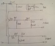
@lrisbo @wolf_teeth Here is an example of the sort of notch several of us are talking about. It appears to function the same as what @lrisbo suggests, it would be great if he could confirm.

yes, this is the way to notch when also wanting to reduce the motor distortion harmonics at the notch frequency.
Please see the app note for the explanation. In short: the motor distortion can be modelled as a voltage source is series with the driver. the driver converts current (not voltage) into sound pressure. Hence, the current caused by the motor distortion voltage source is a proxy for the distortion appearing in the sound pressure. When the driver sees a high impedance then the conversion of voltage to current (sound pressure) has a low gain ( 1/impedance). when the high impedance aligns with the driver peak (at f_peak) then the n’th harmonic distortion generated at f_peak/n is suppressed.
the alternative notch in the form of a series tank added across with the driver is providing a very low impedance at the peak frequency. This means that there is a strong conversion of the motor distortion to sound pressure.
The double kill/whammy is shorting the driver at the peak frequency and will thus not reduce the harmonics generated at fpeak/n so this is not recommended.
All notch types (passive as well as active) reduce the distortion generated at the peak frequency - this follows trivially from reducing the drive level at this frequency.
I hope that helps.
Cheers
Lars/Purifi
Last edited by a moderator:
just to be clear: both the woofer and mid notch is of the ‘wrong’ type that does not reduce distortion
Last edited by a moderator:
Sorry, maybe I missunderstand the problem you trying to tame. But the 10uF paralell capacitor in midrange is to roll it off before the cone breakup that is at around 5K Hz. Once I asked the people at Dynabel if I could change the 10uF to 8.2uF ( I was thinking trying a new cap that hade biggest value at 8.2uF ). The answer was, NO, dont do that. The 8.2uF would have given cutoff at 5558Hz, and that was to high to tame the break up of the cone.
Last edited by a moderator:
The 10uF across the midrange sets the upper corner frequency and the 10uF in combination with the 0.1mH in series forms a resonance which notches. you could reduce the 10uF to 8.2uF and retune the small inductor to still preserve the notch frequency. But the change to 8.2uF affects the overlap with the tweeter and the filter here should be adjusted as well to get the correct summation and phase
This makes sense ( reducing the current ) wondering if you can sketch a Example of the correct way to tackle the problem , or conversely point to a example of someone who has addressed this problem as you suggested. much appreciated stevejust to be clear: both the woofer and mid notch is of the ‘wrong’ type that does not reduce distortion
Hi Steve, we did an app note on the technique. cheers, Lars
https://purifi-audio.com/wp-content/uploads/2022/03/220211_R05-Notchfilter.pdf
https://purifi-audio.com/wp-content/uploads/2022/03/220211_R05-Notchfilter.pdf
I'd wager if they could fix the breakup, then they could charge more and have created a market leader in the W line with the enhanced motor. Ribbed cones aka SB Acoustics NAC/NBAC line seem to have helped here and I would have thought tooling to achieve wouldn't have increased costs significantly.They have to keep costs down.
dave
I suppose if the L/W range weren't any good (as is), we'd have seen them pulled from the market years ago.
Water proofing from party beer spillage 🙂....then what is aluminium providing?
I'm not sure paper cones are pistonic in their passband. I don't know how one can isolate non-linear distortion products from motor, cone and suspension (split by spider and surround) to know how much "better" a stiffer cone is at reducing non-linear distortion due to less / no flex.
The cone does not produce harmonic distortion by flexing/breakup. The problem being discussed is that the breakup peak is louder at some angles, which is a linear phenomenon.
The issue from this is that harmonics at that frequency can excite this resonance the same way that the normal amplifier signal can. This does not produce more distortion, but it appears as though it does.
Breakup doesn't always show peaks, and peaks don't tell the full story about the breakup.
The issue from this is that harmonics at that frequency can excite this resonance the same way that the normal amplifier signal can. This does not produce more distortion, but it appears as though it does.
For all intents and purposes they can be. That said, polar measurements would be helpful here to establish the nature and the magnitude of breakup issues.I'm not sure paper cones are pistonic in their passband.
Breakup doesn't always show peaks, and peaks don't tell the full story about the breakup.
This thread has been very interesting for me, thanks.
A very popular speaker/cabinet for Bass Guitar players is the Hartke line, fully based on Aluminum cone speakers.

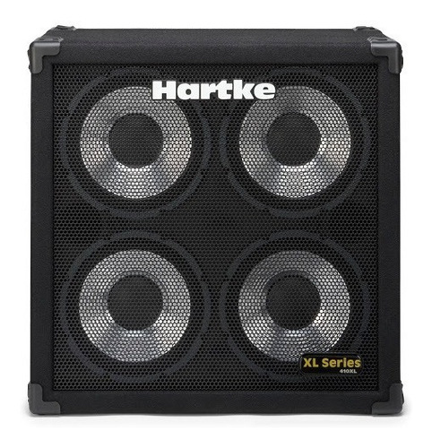
A very popular speaker with Bass Guitar slappers, who hit strings hard against pickups or frets to create clicking harmonics; never measured one, but now I can easily imagine a strong peak, lower in frequency than yours so well within Audio band (say between 3kHZ and 5kHz?).
In this particular case, untamed on purpose, an asset way more than a handicap.
Notice they BRAG about "Transient Attack" 🙂
Just for reference, a short but funny video showing how MOST Bass Players go through a heavy Slap phase 😉
Or more than one 🙄 😉
A very popular speaker/cabinet for Bass Guitar players is the Hartke line, fully based on Aluminum cone speakers.
A very popular speaker with Bass Guitar slappers, who hit strings hard against pickups or frets to create clicking harmonics; never measured one, but now I can easily imagine a strong peak, lower in frequency than yours so well within Audio band (say between 3kHZ and 5kHz?).
In this particular case, untamed on purpose, an asset way more than a handicap.
Notice they BRAG about "Transient Attack" 🙂
Just for reference, a short but funny video showing how MOST Bass Players go through a heavy Slap phase 😉
Or more than one 🙄 😉
(if question addressed to me)Interesting. 🙂 Out of curiosity, what did it do to the HD amplification in the passband?
I'm not equipped to measure distortion but listened carefully to music for clarity and realism against my collection of tweeters including expensive Paradigm Studio Be which came closest. In the end the right match for the 6.5" resin-coated-CF was active electrostatic >8khz (itself a bookshelf-speaker with baffle-size waveguide). Listening to test tone HF flat to ~7.5khz then fell quickly (after 0.68mH LPF nominal 4ohm). Before plast the cone breakup occurred ~4khz then no HF.
The overall sound was of course quite dry and clear (matched my Lowther PM6A except in sensitivity unless doubled), and effortlessly went down deeper than my acoustic music in ~10L sealed Sub enclosure. It is a "famous" diy Sub driver in China. To add warmth I used a vintage English bigbutt alnico 4x7 after LPF, hence Ultrae (ultra sultry).
As for the fiberglass honeycomb 4/5.5/8" drivers, by-ear their respective breakup frequencies 2/5/7khz matched the FR charts of same-looking-membrane drivers from Mivoc/Eve Audio. The Mivoc 4" after 7khz breakup went all the way to 17khz just very uneven. After plast front-or-back-of-cone it was flat to >9khz, after plast rosette waveguide went to at least 12.5khz my hearing limit at low SPL.
Cheap and reversible too.
p.s. Earlier I had tried unsuccessfully to bleed-off breakup resonance by trial-and-error using standard LRC.
Last edited:
In theory, (reality IME) they are for polar response matching XOs, but AFAIK only truly pistonic out to their upper mass corner (Fhm = 2x Fs/Qts') where T/S theory peters out.Water proofing from party beer spillage 🙂
I'm not sure paper cones are pistonic in their passband.
Fs/Qts gives no information on the cone breakup what so ever. It’s the Energy Bandwidth Product of a driver. this is am indicator for the bass extension possible for sealed and reflex and bandwidth for horn loaded. A google search for fhm/upper mass corner gives this old post from you which is about horn loading :In theory, (reality IME) they are for polar response matching XOs, but AFAIK only truly pistonic out to their upper mass corner (Fhm = 2x Fs/Qts') where T/S theory peters out.
https://www.diyaudio.com/community/threads/simple-question-to-horn-speaker.132123/#post-1643579
Where do these terms come from? any reference? would be interesting to know
- Home
- Loudspeakers
- Multi-Way
- Taming SEAS metal woofer Break up ?