Energy Bandwidth Product of a driver. this is am indicator for the bass extension possible for sealed and reflex and bandwidth for horn loade
And is a poor measure.
dave
depends on how you use it. For example:And is a poor measure.
dave
fc=Qb•EBP for sealed boxes. this equation is exact. for B2 sealed we have F3=0.701•EBP.
for reflex the ratio F3/EBP depends on the alignment (which depends on Qts)
GM's talking about 2Fs/Qts, aka Fhm or the mathematical mass-corner frequency of the driver.
Keele for e.g. lists it in his '77 paper Low Frequency Horn Design using Thiele/Small Parameters'.
http://www.xlrtechs.com/dbkeele.com/PDF/Keele (1977-05 AES Preprint) - LF Horn Design Using TS Paras.pdf
Defined as (-3dB) upper rolloff corner frequency from driver Mms.
It's found in other papers too -there are sometimes variations on the equation depending on which fundamental & small signal parameters are used for the derivation, & how far it gets broken down (Keele provides a more detailed initially, then on p.13 simplifies to the familiar 2Fs/Qts)
but representing the same thing in this context. Unfortunately, the acronym 'Fhm' is sometimes also used in other papers to define the completely different upper low pass corner frequency of a bass horn, which can cause some confusion!
Last edited:

it is a useful parameter. however, very misunderstood. the common notion that EBP helps chose the best type of box is nonsensical since EBP has the unit Hz. Qts remains the relevant prameter for choosing alignment.I never pay any attention to it.
dave
thanks 🙏GM's talking about 2Fs/Qts, aka Fhm or the mathematical mass-corner frequency of the driver.
Keele for e.g. lists it in his '77 paper Low Frequency Horn Design using Thiele/Small Parameters'.
http://www.xlrtechs.com/dbkeele.com/PDF/Keele (1977-05 AES Preprint) - LF Horn Design Using TS Paras.pdf
Defined as (-3dB) upper rolloff corner frequency from driver Mms.
It's found in other papers too -there are sometimes variations on the equation depending on which fundamental & small signal parameters are used for the derivation, & how far it gets broken down (Keele provides a more detailed initially, then on p.13 simplifies to the familiar 2Fs/Qts)
but representing the same thing in this context. Unfortunately, the acronym 'Fhm' is sometimes also used in other papers to define the completely different upper low pass corner frequency of a bass horn, which can cause some confusion!
That is far from the truth. cone break up and the associated excessive flexing is a source of distortion. This means that harmonic distortion is generated at and peaks at the breakup frequency.The cone does not produce harmonic distortion by flexing/breakup.
the breakup peak may amplifier harmonics generated in the motor system as we have discussed and these harmonics are generated at sub multiples of the breakup frequency
That is very true. a breakup is also known as an eigenmode and can be viewed as complex pole pair in a lumped (finite order) system. If the zeros of the system are lucky then there is no FR peak. However, the zeros of the speaker system depend on the angle and therefore the breakup peep may suddenly show up off axisFor all intents and purposes they can be. That said, polar measurements would be helpful here to establish the nature and the magnitude of breakup issues.
Breakup doesn't always show peaks, and peaks don't tell the full story about the breakup.
Ah. Breakup itself is linear. Breakup, and the amplitudes it gives are the primary effect, the linear result that amplifies the harmonics of lower frequencies. Would materials distortion not produce harmonics that are above the breakup frequency?cone break up and the associated excessive flexing is a source of distortion.
i guess you can phrase it like that. if the amplitude is low enough then the system is practically linear (unless there are pathological issues like zero cross distortion etc).Ah. Breakup itself is linear. Breakup, and the amplitudes it gives are the primary effect, the linear result that amplifies the harmonics of lower frequencies. Would materials distortion not produce harmonics that are above the breakup frequency?
So we have two effects of a breakup peak:
a) amplification of motor harmonics coincinding with the peak frequency. this is the distortion that can be reduced by using a notching network that provides higher impedance to the driver at the peak frequency
and
b) generation of harmonics when driven at the peak frequency. this gives harmonics at multiples of the breakup frequency and shows up as a THD peak in the usual THD graphs where the x axis is the input (generating) frequency. Thi distortion is typically reduced when the peak is EQ’ed flat so that the flexing i reduced. that goes for any type of EQ/notch
hope it’s clearer now?
Hey Dave did you get a chance to look at the 4 ohm version ?If I get time later today, I'll trace and load the 4 ohm driver ZMA and see what it does to the frequency response.
The good thing about Seas drivers, is their production consistency. A bottomless series notch (the leg that has the 7.47uF and 0.05mH) needs to be precise - meaning if you have drivers made from a company that has variable consistency - you must measure each driver to precisely hit the breakup.
Therefore a notch designed for one system should work well in another using Seas.
Yes I did. I'll post up some images soonHey Dave did you get a chance to look at the 4 ohm version ?
Nice looking forward to the post hey related, no one has commented on the tweeter Adam Recommended any thoughts ?Yes I did. I'll post up some images soon
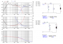
The top 2 windows are the crossover and response for the 4 ohm version. I traced the graph from the madisound sale page, so I can't guarantee this is accurate.
The bottom 2 windows are the crossover and response for the 8 ohm version.
The notch is the 8 ohm resistor in series with the 340nF (or 0.34uF) capacitor.
The reason the notch works for both, is the impedance for both 8 and 4 ohm versions are almost identical at the required frequency. I included an overlay of the impedance of each driver below Black = L15 8 ohm and Red = L15 4 ohm
Should I see this in Isolation, that is that the notch filter only ? or did you apply the entire crossover for the 8om version to the 4ohm version?
Last edited by a moderator:
The series notch - is designed to be paralleled with your low pass inductor. By itself - it doesn't work as the 8 ohm resistor in series attenuates everything..Should I see this in Isolation, that is that the notch filter only ? or did you apply the entire crossover for the 8om version to the 4ohm version?
Here's a simplified version of the crossover, which just uses a single 1mH inductor, allowing the series notch to be effective.
Here's the response. Blue = raw L15 4 ohm, black = with above crossover:
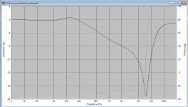
Here's the transfer function of the above filter. Black is the above crossover, red is with the notch removed (thus leaving just the effect of the 1mH series inductor). this shows where the notch is "Striking"
PS: the cap in the notch should have been 0.44uF (not 0.34uF).
Attachments
I couldn’t see it mentioned anywhere above, but if you need more attenuation at the peak, you can also use two parallel (R//L//C) notch filters in series with each other.
This is a parallel notch or a tank. Series notches are components in series and placed across the driver.The series notch - is designed to be paralleled with your low pass inductor. By itself - it doesn't work as the 8 ohm resistor in series attenuates everything..
Here's a simplified version of the crossover, which just uses a single 1mH inductor, allowing the series notch to be effective.
View attachment 1125405
Here's the response. Blue = raw L15 4 ohm, black = with above crossover:
View attachment 1125407
Here's the transfer function of the above filter. Black is the above crossover, red is with the notch removed (thus leaving just the effect of the 1mH series inductor). this shows where the notch is "Striking"
View attachment 1125408
PS: the cap in the notch should have been 0.44uF (not 0.34uF).
- Home
- Loudspeakers
- Multi-Way
- Taming SEAS metal woofer Break up ?