Pass DIY Addict
Joined 2000
Paid Member
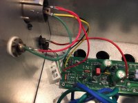
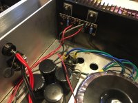
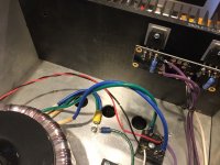
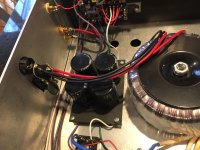
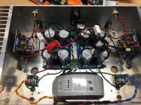
If you have a scope, it is easier to see what kind of noise you are dealing with. This helps suggest the path forward for removing noise. Sometimes noise is from too much ripple and moving from CRC to CRCRC will help. Other times noise comes from the rectifier and changing the types of diodes and/or adding snubber resistors and caps helps. In your image, I see both primary and secondary wires that carry AC that are not tightly twisted together. This has potential to introduce noise. I've had an amp that makes noise with a hard connection between Mains earth and PSU ground that went away when I inserted a thermistor. Other times, this type of noise needed a diode to make it go away. It tends to be a largely trial and error process. The more test equipment you have, the more you might be able to eliminate potential paths of exploration.
I'll give the wires a twist. That's easy enough!
I have 3 thermistors in the amp, 100% like the First Watt power supply design.
How to get my hands on a scope.... I'll have to figure that out.
I have 3 thermistors in the amp, 100% like the First Watt power supply design.
How to get my hands on a scope.... I'll have to figure that out.
The next conquest - I picked these up from a friend last night to work on them.
2 pairs of Aleph J monoblocs. Mine are Minis, these appear to be the higher power versions.
I'm going from memory on what I saw when I opened them up briefly before loading them into my car.
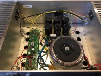
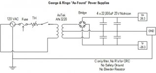
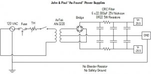
Each one uses a toroid and single rectifier. So one set of secondaries isn't used. One pair may have CRC power supply. One pair looks like C only. No bleeder resistors. No safety grounds. Trannies look like AnTec with 2x 20V Secondaries. My old amp had 25VCT Hammond, now I'm using 2x 15V. I don't know how the 2x20 will do, looks like I'll be learning more about the voltages, resistors, etc as I go through this journey.
One set of boards look like the non-Mini version of the BrianGT boards in my Mini, with snap-off daughter boards. The other pair's boards are long and thin with MOSFETs mounted to heatsinks and hard wired. These look very similar to the ones in one of my Mini-J, where mine use a pair of MOSFETS, and this uses more.
One pair of monoblocks has XLR and RCA connectors. One has RCA's only.
First things first, document PS and amp schematics, measure PS voltage and bias. Then it will be time to make a plan, buy parts, and get to the bench.
Pix and details to follow when I get time to open them up and document them.
2 pairs of Aleph J monoblocs. Mine are Minis, these appear to be the higher power versions.
I'm going from memory on what I saw when I opened them up briefly before loading them into my car.
Each one uses a toroid and single rectifier. So one set of secondaries isn't used. One pair may have CRC power supply. One pair looks like C only. No bleeder resistors. No safety grounds. Trannies look like AnTec with 2x 20V Secondaries. My old amp had 25VCT Hammond, now I'm using 2x 15V. I don't know how the 2x20 will do, looks like I'll be learning more about the voltages, resistors, etc as I go through this journey.
One set of boards look like the non-Mini version of the BrianGT boards in my Mini, with snap-off daughter boards. The other pair's boards are long and thin with MOSFETs mounted to heatsinks and hard wired. These look very similar to the ones in one of my Mini-J, where mine use a pair of MOSFETS, and this uses more.
One pair of monoblocks has XLR and RCA connectors. One has RCA's only.
First things first, document PS and amp schematics, measure PS voltage and bias. Then it will be time to make a plan, buy parts, and get to the bench.
Pix and details to follow when I get time to open them up and document them.
Attachments
Pass DIY Addict
Joined 2000
Paid Member
Though frustrating at the time, trouble shooting is a GREAT way to learn. I made a wiring mistake on my very first amplifier project and managed to let the magic smoke escape from a number of parts. Thus, it turned into a problem solving experience at the same time. I was very unhappy, but I learned quite a bit in the process.
I can’t begin to express how happy I am that somebody is taking the Rawson monstrosities and getting them wired properly in both the AC mains side, and the rest. One of your amps was the topic of a discussion some years ago and the AC is scary enough that we told the interested party to avoid it entirely.
You are doing a good turn for the community at large getting these straightened out.
🙂
You are doing a good turn for the community at large getting these straightened out.
🙂
So true. It's good these are being rebuilt properly.
It's troubling that sometimes you see on other forums people taking offence
from being told their Rawson amps are unsafe, as if the use of a proper earth
connection is optional or controversial.
Dennis
It's troubling that sometimes you see on other forums people taking offence
from being told their Rawson amps are unsafe, as if the use of a proper earth
connection is optional or controversial.
Dennis
Back to TallBoy amp. I don't have a scope - so I did a quick test by ear.
60HZ test tone - lower than my buzz. Not the culprit.
Found a 120Hz tone, and this sounds more like it. I guess that points to PS.
I'll twist the xformer wires.
Now I'm running GBPC3502 bridges. Any guidance on adding snubbers with those bridges?
I have the DIY Audio Universal Power Supply diode boards, too. I could use those instead of the bridges. Any suggested favorite flavor diodes? Is there a successful recipe with sunubbers there?
There is also the output snubber on the CRC board that I have left open. I think that calls for a small cap and resistor. Could that potentially help?
A fast diode will most likely keep ringing to a minimum. Snubber can be quickly measured with Quasimodo jig and a scope. But you need the scope.
This would work nicely - MBR10L60CTG ON Semiconductor | Mouser
Output snubber worthless for Class-A
This is the best $375 you'll even spend on audio - https://www.amazon.com/Rigol-DS1054Z-Digital-Oscilloscopes-Bandwidth/dp/B012938E76
😀 😀 😀
This would work nicely - MBR10L60CTG ON Semiconductor | Mouser
Output snubber worthless for Class-A
This is the best $375 you'll even spend on audio - https://www.amazon.com/Rigol-DS1054Z-Digital-Oscilloscopes-Bandwidth/dp/B012938E76
😀 😀 😀
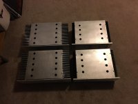
This is the part of the story where we introduce more characters. They are twin cousins to TallBoy and Shorty.
Meet John, Paul, George, and Ringo.
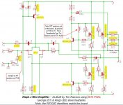
John and Paul have silver heatsinks, and are twin cousins to TallBoy. They have the Silver Heatsinks, and use the same base 327791 PCB’s as TallBoy, with the MOSFETS mounted in a more “freestyle” fashion.
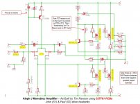
George and Ringo have the black heatsinks, and are twin cousins to Shorty. They have the black heatsinks, and use what appears to be a different generation Aleph board that looks related the BrainGT boards in my “shorty” amp. Except these have the snap off boards for the MOSFETS.
We’ll come back to TallBoy and Shorty in another scene. There’s more work to do there. I’m going to ensure the hot is fused, not neutral. I’ll be twisting toroid wires, playing with rotating the tranny, adding more ground wires between the PSU boards, tweaking how the thermistor is connected to chassis, and putting in fast diodes. If that doesn’t get me where I want to go, I’ll look into a scope, Quasimodo, snubbers. If THAT doesn’t work, I’ll be back for more. Perhaps CRCRC? Perhaps more work on grounding?
Back to John, Paul, George, and Ringo. You’ll see the wiring needs updating for safety. One pair has CRC PS, so I may work with that as a start. They all will need upgrading diodes and making the wiring safer. I actually need to listen to them, too. That’s one thing I haven’t done yet.
I’m back to one question that bugs me. What is with the 3 Ohm resistors on the negative speaker terminals? Any ideas? Can I remove it?
I documented them with "As-Found" Schematics you can see. Some of the resistors look to be values that were likely in Tim's stash. Close enough, I'd guess. Transistors were probably what was available at the time. They also follow the "freewheeling" philosophy on the missing bias adjustment pot/resistor. I highlighted items in yellow that deviate from the base Aleph J schematic.
Thoughts or suggestions for John, Paul, George, and Ringo?
Meet John, Paul, George, and Ringo.
John and Paul have silver heatsinks, and are twin cousins to TallBoy. They have the Silver Heatsinks, and use the same base 327791 PCB’s as TallBoy, with the MOSFETS mounted in a more “freestyle” fashion.
George and Ringo have the black heatsinks, and are twin cousins to Shorty. They have the black heatsinks, and use what appears to be a different generation Aleph board that looks related the BrainGT boards in my “shorty” amp. Except these have the snap off boards for the MOSFETS.
We’ll come back to TallBoy and Shorty in another scene. There’s more work to do there. I’m going to ensure the hot is fused, not neutral. I’ll be twisting toroid wires, playing with rotating the tranny, adding more ground wires between the PSU boards, tweaking how the thermistor is connected to chassis, and putting in fast diodes. If that doesn’t get me where I want to go, I’ll look into a scope, Quasimodo, snubbers. If THAT doesn’t work, I’ll be back for more. Perhaps CRCRC? Perhaps more work on grounding?
Back to John, Paul, George, and Ringo. You’ll see the wiring needs updating for safety. One pair has CRC PS, so I may work with that as a start. They all will need upgrading diodes and making the wiring safer. I actually need to listen to them, too. That’s one thing I haven’t done yet.
I’m back to one question that bugs me. What is with the 3 Ohm resistors on the negative speaker terminals? Any ideas? Can I remove it?
I documented them with "As-Found" Schematics you can see. Some of the resistors look to be values that were likely in Tim's stash. Close enough, I'd guess. Transistors were probably what was available at the time. They also follow the "freewheeling" philosophy on the missing bias adjustment pot/resistor. I highlighted items in yellow that deviate from the base Aleph J schematic.
Thoughts or suggestions for John, Paul, George, and Ringo?
Attachments
-
 John S1 Aleph J Mono 04.jpg650.7 KB · Views: 85
 -
 John S1 Aleph J Mono 03.jpg579.9 KB · Views: 80
 -
 John S1 Aleph J Mono 02.jpg702.7 KB · Views: 104
 -
 John S1 Aleph J Mono 01.jpg729.8 KB · Views: 105
 -
 George Ringo Amp Schematics.JPG85.9 KB · Views: 81
 -
 Black Aleph Mono Power Supply.jpg47.5 KB · Views: 144
 -
 John Paul Amp Schematics.JPG81.4 KB · Views: 152
 -
 Silver Aleph Mono Power Supply.jpg49.4 KB · Views: 153
 -
 Aleph J HELP.JPG89.2 KB · Views: 150
And now some pix of the black heatsink amp "George"
Attachments
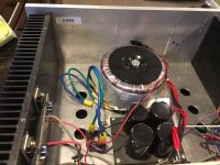
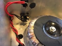
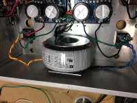
Holy crap the transformer secondary is made a C.T. directly on the chassis.
Don't plug that one in anymore.
Don't plug that one in anymore.
Back to Shorty.
I thought I would try some things from this thread/board and some ideas from some calls with Jim T (6L6) before making a parts order. I’ve been too busy all week to sit down and make a shopping list and look up parts at Digikey. And let's work with what I have first. Maybe the fix will be free? Wishful thinking.
First wave of changes:
o RCA Negative to Chassis = ~13.9 Ohms
o Speaker Negative to Chassis = ~13.9 Ohms
o IEC gnd pin to chassis = 0
Still hums.
Next: remove RCA input ground wire use the pigtails to go to PSU ground directly. No change.
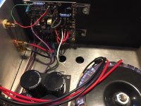
Next – cheap and dirty (and temporary!) CRCRC filter. I used the ground pigtails and cut the V+ and V- wires. I got a couple 22000uF caps from the original amp board and some 0R22 5W sand resistors from another amp and put it together. Double sided foam tape to hold it together. Voltage dropped from +/- 19.9 to +/- 19.37 at the rails. Check DC Offset and Bias. Plays music. All good.
Still Hum.
Crack a(nother) beer and search more threads with “aleph” and “hum” as key words. Wow, I’m not the only one!
Lift one RCA input ground at the connector = louder hum
Tried 14AWG wire between RCA Input Grounds with and without one of the RCA grounds connected. Hum
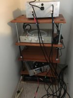
I read something about shielded interconnects and problems. I make my own interconnects using Belden 1505F (RG-59/U Coaxial Cable 22 AWG Stranded Copper Conductor Dual Shield 75 Ohm), so this got my interest. The ones on my bench are about 1M, and are connected a Sonos Connect direct to the amp. That’s how I’ve been testing. Sonos to amp to some cheap Yamaha surround speakers I pulled out of my living room.
I found a vintage pair of Radio Shack RCA’s a nearby box and decided to try those. When I unplugged an RCA things changed – hum volume was not the same. This got me thinking. Perhaps I have a ground loop related to the inputs?
Take a step back, let’s take a different approach. First I played with this on my bench, then I confirmed it on my horns:
Both RCA inputs shorted – quiet
1 RCA Shorted, one RCA Open (nothing connected at all): Short channel = quiet, open = hum
1 RCA Shorted, one RCA connected to preamp. Both quiet
Both RCA’s to preamp = hum
One RCA to Preamp, one RCA open. 1 quiet, 1 hum.
So – based on that… What should I look at next?
Something in the amp?
Jensen Isomax or some DIY equivalent?
I bought a Quasimodo board from MPAudio today. I put together the parts BOM. And I’ll need a scope.
I was also going to get some Schottky’s to replace my diode bridges and play with the power supply some more.
Before I buy the scope, any ideas based on the inputs?
I thought I would try some things from this thread/board and some ideas from some calls with Jim T (6L6) before making a parts order. I’ve been too busy all week to sit down and make a shopping list and look up parts at Digikey. And let's work with what I have first. Maybe the fix will be free? Wishful thinking.
First wave of changes:
- Flipped the transformer around and twisted secondary wires, played with flip/flopping secondary wires
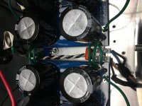
- Added more ground wires between PSU boards (now 6 total)
- Swapped 1k resistor and trim pot between R7/R8 positions
- Test and turn DC Offset down. ~3mV on one channel, ~2mV on the other when cool
- Added 2 more ground wires to play with some grounding at RCA’s (left them taped up).
- Put Thermistor right on the PSU board and down to chassis. Shortended earth ground wire. Both connect at one screw between PSU boards now.
- Checked the grounding with the CL60 place.
o RCA Negative to Chassis = ~13.9 Ohms
o Speaker Negative to Chassis = ~13.9 Ohms
o IEC gnd pin to chassis = 0
Still hums.
Next: remove RCA input ground wire use the pigtails to go to PSU ground directly. No change.
Next – cheap and dirty (and temporary!) CRCRC filter. I used the ground pigtails and cut the V+ and V- wires. I got a couple 22000uF caps from the original amp board and some 0R22 5W sand resistors from another amp and put it together. Double sided foam tape to hold it together. Voltage dropped from +/- 19.9 to +/- 19.37 at the rails. Check DC Offset and Bias. Plays music. All good.
Still Hum.
Crack a(nother) beer and search more threads with “aleph” and “hum” as key words. Wow, I’m not the only one!
Lift one RCA input ground at the connector = louder hum
Tried 14AWG wire between RCA Input Grounds with and without one of the RCA grounds connected. Hum
I read something about shielded interconnects and problems. I make my own interconnects using Belden 1505F (RG-59/U Coaxial Cable 22 AWG Stranded Copper Conductor Dual Shield 75 Ohm), so this got my interest. The ones on my bench are about 1M, and are connected a Sonos Connect direct to the amp. That’s how I’ve been testing. Sonos to amp to some cheap Yamaha surround speakers I pulled out of my living room.
I found a vintage pair of Radio Shack RCA’s a nearby box and decided to try those. When I unplugged an RCA things changed – hum volume was not the same. This got me thinking. Perhaps I have a ground loop related to the inputs?
Take a step back, let’s take a different approach. First I played with this on my bench, then I confirmed it on my horns:
Both RCA inputs shorted – quiet
1 RCA Shorted, one RCA Open (nothing connected at all): Short channel = quiet, open = hum
1 RCA Shorted, one RCA connected to preamp. Both quiet
Both RCA’s to preamp = hum
One RCA to Preamp, one RCA open. 1 quiet, 1 hum.
So – based on that… What should I look at next?
Something in the amp?
Jensen Isomax or some DIY equivalent?
I bought a Quasimodo board from MPAudio today. I put together the parts BOM. And I’ll need a scope.
I was also going to get some Schottky’s to replace my diode bridges and play with the power supply some more.
Before I buy the scope, any ideas based on the inputs?
Attachments
Last edited:
Pass DIY Addict
Joined 2000
Paid Member
Wow - you've been busy here! A few thoughts about places to look - I'm making a bit of a stab in the dark here...
Are you using the original bridge rectifiers or have you tried using known/new ones? I've had some issues with a rectifier that was on the edge of failing and it introduced lots of transformer groan that was coming through the speaker outputs.
Are you certain that the output mosfets are properly insulated? Might be worth removing the boards and checking the physical area where they are mounted to make sure they are smooth, no unintentional grounds, no holes/piercings in the silpad?
How about the RCA input jacks? If they are not fully isolated, you could be introducing ground hum.
I'm just trying to extend the generally poor construction techniques that you've highlighted to other areas of the construction...
Eric,
Bridges are new as of last month.
I measured RCA's to Chassis and Amp ground. All as expected.
Nothing looked wrong when I had the MOSFETs out. Insulators and heatsinks looked fine. That was all torn out and reassembled yesterday. I'll be doing another teardown / rebuild this weekend to take out the extra RC in the CRCRC and fix up the wires I clipped. I'll have another look.
As an aside, maybe place that terminal block on something non-conductive for safety. It looks like a bit of uninsulated wire poking out, if that gets in touch with your chassis the hum is the least of your problems 😉
What happens if you lift the ground connection from one of the channels to the PSU with a resistor (just for testing)?
What happens if you lift the ground connection from one of the channels to the PSU with a resistor (just for testing)?
Last edited:
Tak! The Terminal block wiring with be cleaned up when do the CRCRC to CRC surgery.
I'll try the resistor trick and see what happens. Any idea what value to try? I have some spares from my tube amp building days, so hopefully there is something that can work.
I'll try the resistor trick and see what happens. Any idea what value to try? I have some spares from my tube amp building days, so hopefully there is something that can work.
Thinking way back, my first mini A (the first amp I ever made that didn't have a fire 🙂 ) had hum with similar characteristics. I don't think it was an 'aleph' thing though 🙂
I recall taking the psu ground to one channel, then bringing the ground from that channel to the other channel. 'series' ground I guess....
it did work .
I recall taking the psu ground to one channel, then bringing the ground from that channel to the other channel. 'series' ground I guess....
it did work .
https://www.updatemydynaco.com/documents/GroundingProblemsRev1p4.pdf
Figure 4 and 5 explain ground loops and a way to reduce there impact. You can see that L1, L3, L4, L5 and L6 work as a single transformer.
Figure 4 and 5 explain ground loops and a way to reduce there impact. You can see that L1, L3, L4, L5 and L6 work as a single transformer.
- Status
- Not open for further replies.
- Home
- Amplifiers
- Pass Labs
- Taming Hum on two pre-owned Aleph Mini's