Some create them for you, but with some you need to take a screenshot and use SPLtrace (from FRDconsortium website) to trace the impedance to a text file, then the phase, then merge by hand (or automate if you can). You need to decide on the number of data points to settle on and make sure you can get that kind of resolution for best results.how to create a "zma" file using WT2
If you want to go active, you can use a zma file that has all the same values (simulating a resistor).
Mount them on a suitable baffle and rotate it as you measure.So, how do you tell which way is 90 degrees and which way is 60 degrees on the ME20 and ME10 horns? I can't tell for sure and there are no marks or suggestions on the data sheets.
If you can get a zma file I would work out the six values for you, or there is plenty of help here if you want to use the spreadsheet yourself.Is there a way to calculate a notch filter using the data from this chart? Do I need other data also?
This crossover crosses electrically at around 2k, and there is no correction for the peaks.Thanks. What is the crossover frequency for the Unity Horn
If you can get a zma file I would work out the six values for you, or there is plenty of help here if you want to use the spreadsheet yourself.
Hi Allen! Thank you so much! See attached zma file. It's just a small text file. I can get the "frd" file also through WT2 but have not figured that out yet.
Attachments
Mount them on a suitable baffle and rotate it as you measure.
B&C got back to me. See the attached file. What a great company!
Quote:
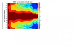
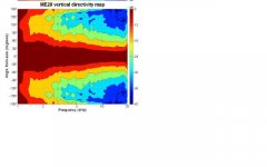
"Looking at the horn throat flare, the plane that intercepts the smallest dimension is that with the widest dispersion coverage. This is true for all the horns.
For example the ME20 ( see attached file) has a rectangular slot at the throat: the smaller axis falls on the widest dispersion plane (90° which is the horizontal plane in the drawing), the larger axis falls on the smallest dispersion plane (60° which is the vertical plane)."
Attachments

Amps are cheap, for example gainclones and lately I've been a fan of Sure class d. $50 for 4 channels(!) 100w each!, add $30 smps.
I'm not sure those are hifi as compared to say the Marchand 50 watt amps.
Why not use active xo? Then you'd care only the acoustic output and impedance becomes irrelevant.
A minidsp for $100 allows for 2-way. That is cheaper than passive in many cases.
While MiniDSP is a great idea, I'm not so sure that doing multiple D/A conversions is a good idea. What chipset do they use? I have a Little Dot D/A that sounds really wonderful. It has the Wolfson chipset.
Sounds like what is described in this post
On the subject of L-pads, assume your driver's impedance were resistive (and response, flat) for a moment. There would be a single value of series resistor that would give you your needed attenuation. Any lesser value of series resistor could be combined with a certain value of parallel resistor for the same attenuation. The end result would be the same (amp concerns aside).
If you can afford to have some parallel resistance, it is obviously not a bad thing, but I'd hardly call it critical. I wouldn't actually use an L-pad myself. My concern would be that it changes more than one thing at a time and therefore makes the results ambiguous and potentially misleading.
I'm certainly going to need an L pad for the DE250! But, you're correct, the L pad affects both the resonant peaks and the impedance rise due to voice coil inductance in the same way that is described in your link.
I don't know how the L pad would affect the response of any notch filter(s) that may be in circuit as well, nor how to take it into account in designing the notch filters. The resonant peak is far less high the more the driver is attenuated by the L pad.
I need to clarify that I was saying I don't use variable L-pads. I have no such issue with fixed resistors in the 'L' configuration.I'm certainly going to need an L pad for the DE250! But, you're correct, the L pad affects both the resonant peaks and the impedance rise due to voice coil inductance in the same way that is described in your link.
OK, I see a few questions in here. A few points...I don't know how the L pad would affect the response of any notch filter(s) that may be in circuit as well, nor how to take it into account in designing the notch filters. The resonant peak is far less high the more the driver is attenuated by the L pad.
A resistor in parallel will bring the impedance a step closer to being resistive, ie: flat. If you compensate an impedance so it is close to flat then adding parallel resistance will only make it more flat. So here is my take on the order of things as you'll be seeing it if I understand you correctly.
Firstly compensate the parts of the impedance that will affect your crossover, ie the peaks. Second, add parallel resistance if desired. This resistance will only serve to flatten the impedance more, the compensation you did needn't change unless you change the horn/baffle.
When it then comes to designing notch filters for the purpose of dealing with peaks (and let me point out that I'd do it differently, for example using a sim) you can calculate the total resistance using the impedance value (where it is flat) in parallel with the resistor you used. With this number, you can use your text book notch filter.
You're welcome. I would be slightly more confident if the zma file were of a higher resolution, and knowing the horn were in it's final configuration. Still, this should be close. Let me know if anything significant changes.Hi Allen! Thank you so much! See attached zma file. It's just a small text file. I can get the "frd" file also through WT2 but have not figured that out yet.
Edit: by the way, the inductors in the sim have no DC resistance. Real ones do, just subtract it from the resistor values shown.
Attachments
Last edited:
You're welcome. I would be slightly more confident if the zma file were of a higher resolution, and knowing the horn were in it's final configuration. Still, this should be close. Let me know if anything significant changes.
Edit: by the way, the inductors in the sim have no DC resistance. Real ones do, just subtract it from the resistor values shown.
Thank you so much! Time to order some parts!
Parts Express messed up my order, so I'm delayed for another week while I return the wrong part they sent me. Sigh...

It sure is dirkwright, well done.
It's hard to say the 5.1 would be a significant change. When you consider that this circuit was desgined with a 'best fit' attitude toward the somewhat more complex impedance of the driver, you have already achieved this. The effect of this level of tweaking will be quite minor at this point. Besides you'll find more options in a 4.7
It's hard to say the 5.1 would be a significant change. When you consider that this circuit was desgined with a 'best fit' attitude toward the somewhat more complex impedance of the driver, you have already achieved this. The effect of this level of tweaking will be quite minor at this point. Besides you'll find more options in a 4.7
It sure is dirkwright, well done.
It's hard to say the 5.1 would be a significant change. When you consider that this circuit was desgined with a 'best fit' attitude toward the somewhat more complex impedance of the driver, you have already achieved this. The effect of this level of tweaking will be quite minor at this point. Besides you'll find more options in a 4.7
The 5.1 value comes from a combination of resistors to get the resistive value for one of the notch filters you designed. The 1 mH coil I bought has a DC resistance of 0.71 ohms, and that filter calls for 9.5 ohms total resistance, so subtracting yields 8.79. So, I ordered a 5.1 + 3.7 (= 8.8), and it was that 5.1 that didn't show. I substituted a 4.7 and thus the circuit has 8.4 ohms instead.
Now I need to introduce some kind of resistance to attenuate the driver by 14 dB. (DE250 is 108dB and the woofer is only 94)
I can order the parts for the crossover now, thank you very much for your help.
A few measurements might be handy.
You need to take into account such things as the coverage of the horn, the woofer and the baffle, the acoustic gain of the horn and the fact that the response won't likely be flat. If you take measurements you can use them instead. This is regardless of the crossover type... a passive crossover may also be better served designing the whole thing at the same time.
If you want something 'rough and ready', you could use a standard L-pad formula based on 6 ohms. With the addition of at least an appropriate high pass capacitor, you could tweak it into something listenable.
A few measurements might be handy.
You need to take into account such things as the coverage of the horn, the woofer and the baffle, the acoustic gain of the horn and the fact that the response won't likely be flat. If you take measurements you can use them instead. This is regardless of the crossover type... a passive crossover may also be better served designing the whole thing at the same time.
If you want something 'rough and ready', you could use a standard L-pad formula based on 6 ohms. With the addition of at least an appropriate high pass capacitor, you could tweak it into something listenable.
Thanks. I'm getting there. First I need something basic from the formulas, and of course some kind of box for the tweeters! All I've built so far are these woofer boxes!
Attachments
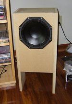
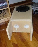
Thanks. I'm getting there. First I need something basic from the formulas, and of course some kind of box for the tweeters! All I've built so far are these woofer boxes!
Diffraction creates a really nasty coloration that makes loudspeakers fatiguing. If you'd like to reduce it, use a roundover on those cabinets and recess that woofer. It makes an audible and measurable difference.
Diffraction creates a really nasty coloration that makes loudspeakers fatiguing. If you'd like to reduce it, use a roundover on those cabinets and recess that woofer. It makes an audible and measurable difference.
They are intended as test boxes only, so I didn't bother with that stuff. I've never built a vented box before so didn't know what to expect. It took a lot for me to even build these, since I didn't have a router, or the circle cutting jig. So, those had to be purchased before I could even build these test boxes. I'd been avoiding buying a router for years because they are like a hall of temptation. There are so many accessories and what not doodads available that it made my head spin and my wallet get nervous. I took the plunge because I had to... now must resist slippery slope... 😱
Probably your earliest requirement would be a baffle for the horn. Preferrably larger, rounded and flush mounted like PB says, but anything would be better than nothing. Personally I'd prefer to build something more permanent so I could have some confidence in my measurements, but a flat board as wide as the woofer box and flush with the top of it would be a start if you're keen to get something happening. A little absorbent damping over it may be worth playing with.
Probably your earliest requirement would be a baffle for the horn. Preferrably larger, rounded and flush mounted like PB says, but anything would be better than nothing. Personally I'd prefer to build something more permanent so I could have some confidence in my measurements, but a flat board as wide as the woofer box and flush with the top of it would be a start if you're keen to get something happening. A little absorbent damping over it may be worth playing with.
Oh sure. That's what I had in mind.
Since I'm cutting off the horn's response before it begins to radiate beyond it's intended 90 by 60 pattern, would absorbent damping material on the baffle make any difference? See the attached horn patterns.
Attachments
Are those from a trusted third party? How would you feel about taking your own?
You'll notice from them that there is quite some energy at 90 degrees. This in itself is neither unusual or necessarily a problem, just an indicator of why you may not want to ignore the baffle.
There seems to be some energy at 180 degrees so I'm wondering about the baffle dimensions on the test set up. This seems to go up to quite a few kHz. In order to avoid a problem you don't want to just cross right where it starts. All in all it would seem the baffle would be important with this design. Personally I'd avoid this horn for a few different reasons, but just my humble opinion.
Last edited:
Are those from a trusted third party? How would you feel about taking your own?
You'll notice from them that there is quite some energy at 90 degrees. This in itself is neither unusual or necessarily a problem, just an indicator of why you may not want to ignore the baffle.
There seems to be some energy at 180 degrees so I'm wondering about the baffle dimensions on the test set up. This seems to go up to quite a few kHz. In order to avoid a problem you don't want to just cross right where it starts. All in all it would seem the baffle would be important with this design. Personally I'd avoid this horn for a few different reasons, but just my humble opinion.
Those charts are from B&C. I'm not sure I know how to take my own. I have a proper microphone and other stuff though. Crossover is 1600 Hz, so I think the horn would maintain directivity down to at least that frequency. I agree it's not the best horn. I would have preferred a tractrix, but could not find one.
- Status
- Not open for further replies.
- Home
- Loudspeakers
- Multi-Way
- T/S for DE250?