Understand that a Zobel for a complex load like a compression driver on a horn is not going to be simple and it certainly won't be just a resistor and capacitor. Crossover design for a compression driver does not fit into any of the standard ways of doing crossovers. And, if the system is Constant Directivity, then the passband of the HP filter is not even flat. This is one of the main reasons that horns have had a bad rep - bad crossovers. I have actually heard of people using just a capacitor. The HP section of one of my crossovers have five caps, three inductors, and five resistors. Simple its not.
I'd like to clarify what I believe is a misunderstanding here. A zobel network, as I understand it is an impedance correction circuit. However, in the speaker building world, it is often taken out of context and used to refer to the series RC circuit used in parallel with a driver to balance the effect of the voice coil inductance. This is of primary concern with low pass circuitry, ie: woofers.
In your case you will be interested in flattening the twin peaks and there will be only one way I could think you'd do that reasonably and successfully... Measure your impedance (with phase), and use either a sim or repeated measurement to design one empirically.
In your case you will be interested in flattening the twin peaks and there will be only one way I could think you'd do that reasonably and successfully... Measure your impedance (with phase), and use either a sim or repeated measurement to design one empirically.
A Zobel is a network that is placed in parrallel to any other network so as to make their combined impedance that of a resistor. There are general theorems about how this can be done for any circuit topology using the concepts of a network "dual". But that gets pretty advanced mathematically. The point that I'd like to make is that a Zobel is in no way a requirement in any situation - any desired response can be achieved with or without it. You just have to know what you are doing.
I'd like to clarify what I believe is a misunderstanding here. A zobel network, as I understand it is an impedance correction circuit. However, in the speaker building world, it is often taken out of context and used to refer to the series RC circuit used in parallel with a driver to balance the effect of the voice coil inductance. This is of primary concern with low pass circuitry, ie: woofers.
In your case you will be interested in flattening the twin peaks and there will be only one way I could think you'd do that reasonably and successfully... Measure your impedance (with phase), and use either a sim or repeated measurement to design one empirically.
A zobel network is also important for midrange drivers. I'm sorry, I'm talking about 3 different drivers in one thread! The Dynaudio D54 is a 2" soft dome midrange driver. It's in a 500Hz tractrix horn designed by Bruce Edgar and has a high frequency roll off at 5 kHz. It's not a compression driver. The image I posted is from the WT2 with calculated zobel on that driver while installed in the horn.
I understand that I need to flatten the twin peaks on the B&C tweeter horns for the high pass filter. I believe I can ignore the impedance rise with frequency due to voice coil inductance on the tweeters, so no zobel is required there. I have yet to start experimenting with notch filters on them.
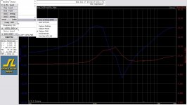
Speaking of twin peaks, I attached an 8 ohm variable L pad to my DE10/ME10 and ran WT2. What I noticed that the L pad would alter both the resonant peak and the inductive rise on the impedance curve, as well as of course changing the phase response. I assume something similar will happen with the DE250, but it has not arrived yet so I don't know for sure. How do I incorporate a notch filter in this arrangement? Do purists just not use variable L pads and stick with fixed ones? The B&C 8NDL51 woofer I'm using has a sensitivity of 94 dB and the DE250 is 108.5 dB. Obviously I need to bring the tweeter down a lot!
The attached chart is the DE10 with variable L pad set to half way. When it was at full up, the response was the same as if it wasn't there.
Attachments
Understand that a Zobel for a complex load like a compression driver on a horn is not going to be simple and it certainly won't be just a resistor and capacitor. Crossover design for a compression driver does not fit into any of the standard ways of doing crossovers. And, if the system is Constant Directivity, then the passband of the HP filter is not even flat. This is one of the main reasons that horns have had a bad rep - bad crossovers. I have actually heard of people using just a capacitor. The HP section of one of my crossovers have five caps, three inductors, and five resistors. Simple its not.
Thanks again for your informed response. That is a lot of components in your crossover!
It seems, based on your reply and my limited experience, that it would be far more simple to just go to an active system with 24dB/octave crossovers and other features like time delay, DSP, etc. Is this commonly done with compression drivers?
A Zobel is a network that is placed in parrallel to any other network so as to make their combined impedance that of a resistor. There are general theorems about how this can be done for any circuit topology using the concepts of a network "dual". But that gets pretty advanced mathematically. The point that I'd like to make is that a Zobel is in no way a requirement in any situation - any desired response can be achieved with or without it. You just have to know what you are doing.
Yes, as I understand it, they were originally used on long signal lines I think in the phone company to cancel the inductive and capacitive reactance of the long cables.
Sounds like what is described in this postSpeaking of twin peaks, I attached an 8 ohm variable L pad to my DE10/ME10 and ran WT2. What I noticed that the L pad would alter both the resonant peak and the inductive rise on the impedance curve,
On the subject of L-pads, assume your driver's impedance were resistive (and response, flat) for a moment. There would be a single value of series resistor that would give you your needed attenuation. Any lesser value of series resistor could be combined with a certain value of parallel resistor for the same attenuation. The end result would be the same (amp concerns aside).
If you can afford to have some parallel resistance, it is obviously not a bad thing, but I'd hardly call it critical. I wouldn't actually use an L-pad myself. My concern would be that it changes more than one thing at a time and therefore makes the results ambiguous and potentially misleading.
I would rather correct the impedance in one fell swoop, then add the smallest parallel resistor I could afford to (if I even bothered), but not saying I wouldn't tweak them for one reason or another if required.
You could start with two series RLC circuits in parallel with your driver. This ought to get you on your feet.How do I incorporate a notch filter in this arrangement?
What's the resolution there? Perhaps going a little finer would give you better control over the results, especially for these peaks.The attached chart is the DE10 with variable L pad set to half way.
Thanks again for your informed response. That is a lot of components in your crossover!
It seems, based on your reply and my limited experience, that it would be far more simple to just go to an active system with 24dB/octave crossovers and other features like time delay, DSP, etc. Is this commonly done with compression drivers?
No contest that for experimentation active is the way to go for Compression Drivers. Passive only makes sense if you are really good at crossver design and you are trying to get to the minimum cost over a large number of systems. Otherwise active (DCX2496 for example) is the way to go. I would not use 24 dB/Oct filters however.
For CD start with a simple first order HP set at about 8-10 kHz. This should get you fairly close to flat along any axis (for non-CD, the freq is lowered until you find the best flatness). Then adjust the gain to match the woofer and you are 80% of the way there. Use various parametric EQs to smooth the response - axial and power as a mixed compromise.
More to think about, just Google:
HOLMimpulse
Jeff Bagby PCD
-----
RTA software is not the way to go for designing crossovers. You have impedance measurement capability via the WT2 to make the zma files, and you can use HOLMimpulse for gated measurements to make the frd files. If you have M$ excel you can PCD till your hearts content.
I accept no responsibility for the impending brainmelt 😀
Why not use active xo? Then you'd care only the acoustic output and impedance becomes irrelevant.
A minidsp for $100 allows for 2-way. That is cheaper than passive in many cases.
A minidsp for $100 allows for 2-way. That is cheaper than passive in many cases.
More to think about, just Google:
HOLMimpulse
Jeff Bagby PCD
-----
RTA software is not the way to go for designing crossovers. You have impedance measurement capability via the WT2 to make the zma files, and you can use HOLMimpulse for gated measurements to make the frd files. If you have M$ excel you can PCD till your hearts content.
I accept no responsibility for the impending brainmelt 😀
I already have Holmimpulse, but don't know how to use it. Is the hardware setup the same as TrueRTA? (I have that - mic, mixer, D/A, etc) I read through some of the documentation that came with it, but it was not clear to me.
Just downloaded PCD, thanks.
When I have time, I'll look into this.
To do list:
- how to create a "zma" file using WT2
- how to create a "frd" file using Holmimpulse
- read documentation for PCD
Why not use active xo? Then you'd care only the acoustic output and impedance becomes irrelevant.
A minidsp for $100 allows for 2-way. That is cheaper than passive in many cases.
I was hoping to keep using my Musical Fidelity 50watt integrated amp, so this two way (B&C 8NDL51 + DE250/ME20, crossed over at 1.6kHz) needs to have a passive crossover. I want to keep the "preamp out" jacks for a subwoofer also.
The 3 way horn system (DE10/ME10 + D54/Edgar horn + 12PE32/home built horn) can be active, in fact probably will be.
Your price does not include the 4 mono amplifiers (or two stereo) I would need for a 2 way active system. It also does not include the cost of a really good preamp. I cannot find any good plate amplifiers that are low power and clean. (50 watts through a DE250 will make you deaf! Heck, 50 watts into the 8NDL51 will make you deaf too!) When you add in the cost of all the amps needed, active becomes expensive. I see that Miniamp's are also available, so that's very doable. Thanks!
Last edited:
So, how do you tell which way is 90 degrees and which way is 60 degrees on the ME20 and ME10 horns? I can't tell for sure and there are no marks or suggestions on the data sheets.
I was hoping to keep using my Musical Fidelity 50watt integrated amp, so this two way (B&C 8NDL51 + DE250/ME20, crossed over at 1.6kHz) needs to have a passive crossover. I want to keep the "preamp out" jacks for a subwoofer also.
The 3 way horn system (DE10/ME10 + D54/Edgar horn + 12PE32/home built horn) can be active, in fact probably will be.
Your price does not include the 4 mono amplifiers (or two stereo) I would need for a 2 way active system. It also does not include the cost of a really good preamp. I cannot find any good plate amplifiers that are low power and clean. (50 watts through a DE250 will make you deaf! Heck, 50 watts into the 8NDL51 will make you deaf too!) When you add in the cost of all the amps needed, active becomes expensive. I see that Miniamp's are also available, so that's very doable. Thanks!
Amps are cheap, for example gainclones and lately I've been a fan of Sure class d. $50 for 4 channels(!) 100w each!, add $30 smps.
OK, I ran WT2 on these DE250's + ME20 horns. I see two impedance peaks, one at about 1800 and another at about 750 Hz. Is there a way to calculate a notch filter using the data from this chart? Do I need other data also? I have only found calculators for either driver resonant frequency, using Re, Qes, Qms, etc, or one that used data from the frequency domain with peak frequency and -3dB points on each side as well as amplitude in dB to design a filter. My intention is to design a second order high pass filter @ 1600 Hz.
Attachments

The data sheet provided by B&C does not list all of the T/S parameters for this driver. Anyone have them?
In order to cross over at the recommended frequency of 1.6kHz, I need a notch filter(s). There are two resonance peaks for this driver, according to their data sheet. So I need at least: Fs, Qes, Qts, and Re. I sent an email to them on Friday but have not heard back yet. Maybe it's holiday in Italy or something. I'm sure they'll get back to me eventually.
Also, does the electrical impedance change when a driver is coupled to a horn? I bought the ME20 horn to go with this driver.
Dirk,
William Cowan has posted a crossover than Danley did for the Unity horn. The dimensions of that horn are similar to the dimensions of your horn, and Danley's crossover might be a good starting point. I believe it uses the DE25 or the DE250 - it should 'get you in the ballpark.'
Details on the crossover are on Cowan's site.
I think the crossover for some of the Geddes speakers has been published on here, I don't have the link handy though.
Rather than do a crossover from scratch I've generally had the best results by taking an existing crossover and then adjusting components. When I've tried doing compression driver crossovers 'from scratch' the results were a bit substandard, particularly due to the zany impedance curve.
Compression drivers and horns are quite tricky - about the only upside is that you have a lot of efficiency to burn so you have the luxury of doing things that you can't do with conventional domes, such as using xover points or slopes that are wacky.
Dirk,
William Cowan has posted a crossover that Danley did for the Unity horn. The dimensions of that horn are similar to the dimensions of your horn, and Danley's crossover might be a good starting point. I believe it uses the DE25 or the DE250 - it should 'get you in the ballpark.'
Rather than do a crossover from scratch I've generally had the best results by taking an existing crossover and then adjusting components. When I've tried doing compression driver crossovers 'from scratch' the results were a bit substandard, particularly due to the zany impedance curve.
Compression drivers and horns are quite tricky - about the only upside is that you have a lot of efficiency to burn so you have the luxury of doing things that you can't do with conventional domes, such as using xover points or slopes that are wacky.
Thanks. What is the crossover frequency for the Unity Horn between the midrange and tweeter? I am not expert enough to understand much of Danley's crossover. I see one series notch filter (25ohm, 1mf, 5mH), but that's all I recognize. I don't know about using someone else's design unless I understand what each part is doing.
Thanks. What is the crossover frequency for the Unity Horn between the midrange and tweeter? I am not expert enough to understand much of Danley's crossover. I see one series notch filter (25ohm, 1mf, 5mH), but that's all I recognize. I don't know about using someone else's design unless I understand what each part is doing.
It's been nearly five years since I used the crossover. I've noticed that a lot of commercial crossovers don't follow textbooks at all, so trying to understand how this works may be difficult without a proper simulator. This is because the combination of the compression driver's impedance curve and the horn is so complex.
The way that I was able to get it to work was by measuring the impedance of my compression driver on a horn, and then create a model of that driver and horn in Speaker Workshop. (Speaker Workshop's crossover simulator is surprisingly good!)
Once I had created a simulation of my compression driver I was able to tweak the components to improve the response. I didn't make any huge changes - tweaked the resistors mostly.
There's a somewhat decent chance you might be able to just hook it up and it will work. It's designed for the DE25 or the DE250, so it's not a stretch really.
- Status
- Not open for further replies.
- Home
- Loudspeakers
- Multi-Way
- T/S for DE250?