There's a lot of newbie talk in my dipole experiment thread (on my part) but hopefully some useful tidbits too. I will start another one very soon for the next project - it will go straight into some fairly well formed ideas, based on experience and strong input from the forum.
T-bass will be central to the design.
Simon
T-bass will be central to the design.
Simon
Hi there guys!
I 2 have finished my T-bass circuit. So far it works very well with Alpha 15''. However, i am using very sensitive alnico oval driver so i need extra 3db louder bass. T-bass brought some gain, but not enough.
Bass improved very much in depth and have more transient response with "groovy" sound 😀
I am using ~350V toroidal trafo with ~35V secondaries.Choke is 6.7mH and i connected 2x1500uF in line. Resistor in line with C is 1.5R. I removed resistor in line with choke.
Third ,small choke is 6db bass crossover but i don't know what value is it. It is just enough to tame mid's a little.
I drive whole rig with Zen-Mod's Babbelfish J .
Thank You Graham for all your effort !
I 2 have finished my T-bass circuit. So far it works very well with Alpha 15''. However, i am using very sensitive alnico oval driver so i need extra 3db louder bass. T-bass brought some gain, but not enough.
Bass improved very much in depth and have more transient response with "groovy" sound 😀
An externally hosted image should be here but it was not working when we last tested it.
I am using ~350V toroidal trafo with ~35V secondaries.Choke is 6.7mH and i connected 2x1500uF in line. Resistor in line with C is 1.5R. I removed resistor in line with choke.
Third ,small choke is 6db bass crossover but i don't know what value is it. It is just enough to tame mid's a little.
I drive whole rig with Zen-Mod's Babbelfish J .
Thank You Graham for all your effort !

Hi Chakija
It's good that you tried the T-bass. It's worth it.
OT: By the way, I completely removed side wings from my OB's (even from the bass, not just midrange), so the whole thing is just a flat piece. You'll get a bit less quantity, but more quality.
Sorry for OT.
Pozdrav 🙂
Vix
It's good that you tried the T-bass. It's worth it.
OT: By the way, I completely removed side wings from my OB's (even from the bass, not just midrange), so the whole thing is just a flat piece. You'll get a bit less quantity, but more quality.
Sorry for OT.
Pozdrav 🙂
Vix
Interesting, I don't think I can afford to do that on my planned speakers, there'd surely not be nearly enough bass 🙁
I think using U-wings to gain more bass(or actually reduce excursion for low freqs) is ok as long as you are not pushing it too far.
As I rule of thumb, I make sure that the quarte-wave resonance of the U-cavity is well above crossover frequency between bass and midrange (that is, wings are short enough: I use some 25 cm for my Alphas and cross at about 150Hz). However, even in this case, I put a notch to equalize the quarter-wave peak out - otherwise it might still be audible.
The trade-offs are well documented on Martin King's web site (quarter-wave.com)
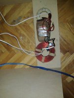
Hi chakija,
Your first pic with the choke and toroid flat beside each other was just fine.
The magnetic fields were already at right angles and the second pic is wrong !
However your capacitors look small. Do go for low ESR 40Vdc rating or higher.
Also your choke might be a good air core but the resistance is probably high. Better use suitable ferrite or iron core, or sometimes the secondary of a 15 to 24V transformer will do at about 3A -check with an inductance meter.
Hi Vix,
Try a cushion either side of the baffle where the wings used to be. Equal front and back !!!
Cheers ........ Graham.
Graham Maynard said:Your first pic with the choke and toroid flat beside each other was just fine.
The magnetic fields were already at right angles and the second pic is wrong !
Yes, because the toroid is wound different.
I returned trafo in previous position...Strangely, it sounds better this way 😀 .Graham, i will try to change capacitors with those u suggested.
I found this T-bass circuit pretty amazing...
I connected it to my FR loudspeaker and got very good result. It is just amazing how much bass this old alnico rag can deliver and again play so clean. I listen it without need to change anything-i feel no need for additional helper even if very low bass is missing.
However Graham ,i would like u to suggest me appropriate values for this loudspeaker because current components are more suitable for Alpha...
Thanks !
Btw. did anyone tried B200 with T-bass ?
chakija said:.......
I connected it to my FR loudspeaker and got very good result. .......
playing with fire , again ?
you'll cry , when you fry them ... I told you .
Hi Zen Mod,
Your comment just made me smile.
The reason speakers get burnt out is because they get fed more power to make them reproduce as the listener thinks they should sound - only cannot !
Even with extra power the drivers still don't sound right and they end up storing/dissipating more energy, which leads to burnout. This was why all PA drivers ended up having to be be re-specified in the 1960s when transistor amplifiers started taking over from tube amplifiers.
Hi chakija,
Yes the T-bass will work just fine with a Fullrange driver which is why it is here. The only aspect to watch out for is mid/hi modulation due to cone excursion, but that is down to common sense, and a Fullrange will sound better and louder with this circuit than it ever could with EQ, digital etc. without it burning out.
Me suggest values ? Sorry no can do.
This is where component values must be tuned to suit individual driver/baffle/room etc.
Don't forget that you can adjust the value of that choke you have in the photo by putting non-ferrous metal inside it to reduce inductance, or the ferrite rod from an AM radio to increase it.
Cheers .......... Graham.
Zen, i really appreciate your concern, but i assure u that i will not exaggerate with precious oval's 
As the time past, i am more and more closer to a plain baffle with only oval FR on it + T-Bass and piezo helper above 14kHz...
Graham, excuse my ignorance...I will try to experiment for best values.
As the time past, i am more and more closer to a plain baffle with only oval FR on it + T-Bass and piezo helper above 14kHz...
Graham, excuse my ignorance...I will try to experiment for best values.
Hi chakija.
If you want to run Fullrange do not use any series output choke; use only the transformer and its input capacitor/choke/resistor drive.
Cheers ..... Graham.
If you want to run Fullrange do not use any series output choke; use only the transformer and its input capacitor/choke/resistor drive.
Cheers ..... Graham.
In future time i will need to reconsider my statements little better before i jump in with conclusion...
After some time listening FR with T-bass ( without series choke 😀 ) ,i think that it brings in some edge in mid's that becomes to irritate after 20 min of listening. Although there is plenty of bass ,it seems that some information is lost+that fatiguing mids. I guess i was so overjoyed with bass that came from my ovals, that i completely depreciated rest of the sound specter. I don't know what could cause this but as i have no time to peck in the dark, i returned T-bass on alphas and added 80uF in parallel along with series choke.
I am pleased again so far...
Hi Chakija,
I have not had time to optimes the circuit for Fullrange, and don't expect to have for the foreseeable future.
The series R and C need to be spliti into two legs - one of which bypasses the transformer above bass frequencies; ie, one R+C from amp to centre tap, ans one R+C or C alone direct to LS.
Did this once but did not make notes, and it does not affect the bass.
Cheers ........ Graham.
I am about to assemble the components for the T-bass circuit but I want to be sure that I get it right. My OB project consists of the B200 and an Alpha 15. The post I have found to be a correct match to my OB is project that Graham posted is this:
http://server6.theimagehosting.com/image.php?img=T-bass.f83.png
I have found an Avel 250v 25v/25v transformer at Parts Express.
The question I have is regarding the 1500 uf cap. On a couple of other posts it was suggested that a cap value of 470 to 660 could be used. Could I use (Parts Express) 100V Non-Polarized Crossover Caps? They have values that go up to 500uf and are very reasonable cost wise. I would normally use Dayton or Solen caps, but they would be quite a bit more.
I also assume that a conventional 18 gauge air core inductor (6.4mh) would be ok.
John
Those caps will be fine. The inductor should not be air-core. It should be some type of transformer or ferrite-core for low DCR, and low cost.
Simon
Simon
Estes said:I am about to assemble the components for the T-bass circuit but I want to be sure that I get it right. My OB project consists of the B200 and an Alpha 15. The post I have found to be a correct match to my OB is project that Graham posted is this:
http://server6.theimagehosting.com/image.php?img=T-bass.f83.png
I have found an Avel 250v 25v/25v transformer at Parts Express.
The question I have is regarding the 1500 uf cap. On a couple of other posts it was suggested that a cap value of 470 to 660 could be used. Could I use (Parts Express) 100V Non-Polarized Crossover Caps? They have values that go up to 500uf and are very reasonable cost wise. I would normally use Dayton or Solen caps, but they would be quite a bit more.
I also assume that a conventional 18 gauge air core inductor (6.4mh) would be ok.
John
Are bi-polars needed here for the e-caps? I think this has been answered before, but have not yet referenced it.
Tea-Bag.
Yes, they must be bipolar, but you can use polarised caps connected in series, which effectively makes them bipolar and changes their capacitance value.
I use two 1000uF electrolytic caps in series, which makes one bipolar cap of 500uF.
Simon
I use two 1000uF electrolytic caps in series, which makes one bipolar cap of 500uF.
Simon
- Home
- Loudspeakers
- Full Range
- 'T'-bass drive for OB LF drivers.