For rails up to about +/-60V and a load of 4R I would recommend MosFets like the IRFB4615. Good body diode, fully specified dv/dt and a better fit to be driven directly from the level shifter rather than the heavy IRFB4227.
In case you intend to offer your home power version as an open design, you are welcome to do so in this thread and I could send you some IRFB4615.
In case you intend to offer your home power version as an open design, you are welcome to do so in this thread and I could send you some IRFB4615.
I was going to use IRF540 as i do not actually have the IRFB4227.
I will indeed share my home power version as an open project if i get it to work.
I've started on a prototype on a prototyping board (audio input and modulator)
For the power section i'll use the power module boards i ordered from itead studio.
If this works out i'll design a board that houses the entire thing.
I've started on a prototype on a prototyping board (audio input and modulator)
 ...active guy...
 The IRF540 is really an unpleasant type for class D.
The body diode is pure pain.
If you would say IRF540Z, it would be great (really!) for rails up to aprrox. +/-40V.
But without the Z...
Everything is possible, but not everything is fortunate.
The body diode is pure pain.
If you would say IRF540Z, it would be great (really!) for rails up to aprrox. +/-40V.
But without the Z...
Everything is possible, but not everything is fortunate.
IRFB5615 and IRFB5620 are ok , I use them with +/-60V and +/-80V @ 700Khz selfoscilating pre+postfilter topology with good results.
Before I bought the 4615 I also read the data sheet of the 5615, because they are advertised particularly for classD.
Gate charge is similar, Rdson is identical, power identical.
But the body diode of the 4615 is by factor 2-3 better and max dv/dt is properly specified, so I failed to understand why IR is promoting the 5615 for classD and ordered the 4615 in a stubburn manner. 😀 ..and found their real life switching behavior pretty nice.
Good to hear that you have positive experience also with the 5615.
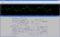
I was doodling around in LTspice to see if i could make it work without the voltage to current converter on the audio input and the quadruple transistor hysteresis window control circuit.
Now if it will work at all in real life i kinda doubt as im gonna assume choco already tried this prior to adding the transistor circuits, but its still interesting.
Why i did this is that while building the choco version, i found out im all out of some of the transistors and i still wanned something i could get together and play around with until i've ordered more transistors.
Attachments
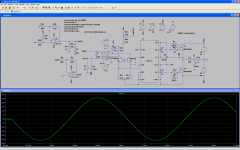
Disregard this!!! Turns out a a opamp was oscillating, making the circuit clocked rather than self osc.
The LT1115 audio opamp model seem a bit buggy.
The LT1115 audio opamp model seem a bit buggy.
For me its the opposite, my simulation likes to lock onto a 1.5MHz switching frequency where changing the cap on the comparator inputs does nothing until it get so large the sim slows down to a mere 100kHz.
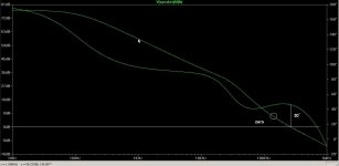
The zero is formed by the two D-portion caps in the feedback.
Means C3 and C4 in the attached sim (respectively C210 and 211 in the real schematic).
I am using the attached way of modelling.
The values are still from the earlier posted version and bode, but V1.3 will not differ fundamentally.
Take care. When simulating large integrating gains you really have to ensure a properly adjusted DC bias situation (already adjusted in the attached file).
Otherwise the sim will just show nonsense of saturated gain stages.
In V1.3 multiple values have changed, also the triangle magnitude is slightly larger. Means the gain of E1 would need to be adjusted slightly.
Attachments
U1 is not inverting, Q2(Q4), E1, E2 are not inverting as well, so the forward path is not inverting? 😕
E1 is used inverting. The table numbers are non inverting, and I am feeding the signal into the neg input pin and take the output from the pos output pin.
 Thank you
In just looking and listening and reading and learning over here.
Hope to try something developed and test it as a 'real' circuit when you get there.
Thx-RNMarsh
Hope to try something developed and test it as a 'real' circuit when you get there.
Thx-RNMarsh
Hi RNMarsh,
the amp is up and running since about one month.
A short overview of the measured performance of the version of the first builders package (V1.3) is given on page 32 in the postings #316...318.
The proper builders package is ready for download on page 33 posting #329.
Enjoy reading
Markus
the amp is up and running since about one month.
A short overview of the measured performance of the version of the first builders package (V1.3) is given on page 32 in the postings #316...318.
The proper builders package is ready for download on page 33 posting #329.
Enjoy reading
Markus
- Home
- Amplifiers
- Class D
- SystemD_2kW, any interest for an open design?